
Spiral membrane element

a membrane element and spiral technology, applied in the direction of moving filter element filters, filtration separation, separation processes, etc., can solve the problems of increasing the winding angle of the glass roving, increasing the outer diameter near the end part of the membrane element, increasing the outer diameter, etc., to achieve the effect of preventing cracks, improving barrier properties, and reducing the number of cracks

Inactive Publication Date: 2009-03-12
NITTO DENKO CORP
View PDF29 Cites 25 Cited by
  • Summary
  • Abstract
  • Description
  • Claims
  • Application Information

AI Technical Summary

Benefits of technology

[0009]Therefore, an object of the present invention is to provide a spiral membrane element that can improve the barrier property of a fiber reinforced plastic layer having a fiber roll as a reinforcing phase and that can effectively prevent occurrence of cracks.Means for Solving the Problems
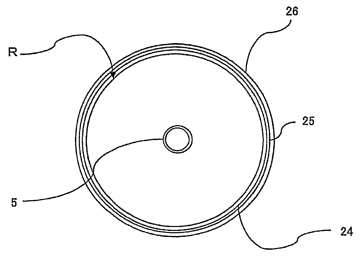
[0011]According to the spiral membrane element of the present invention, a plastic layer is disposed approximately over the entire length and approximately over the entire circumference of the fiber reinforced plastic layer having a fiber roll as a reinforcing phase, so that the barrier property can be improved, and the occurrence of cracks can be effectively prevented. Also, since the plastic layer is not exposed to the surface, damages such as scars are less liable to occur, whereby the reinforcing effect can be maintained for a long period of time.
[0012]In the above description, the plastic layer is preferably a tubular heat-shrinking film. By using a tubular heat-shrinking film, the film can be made to follow well and to closely adhere to even a cylindrical roll whose outer surface has unevenness and whose outer diameter is not constant, whereby wrinkles or distortion is less liable to occur in the plastic layer even at the time of winding a reinforcing fiber on the upper layer.
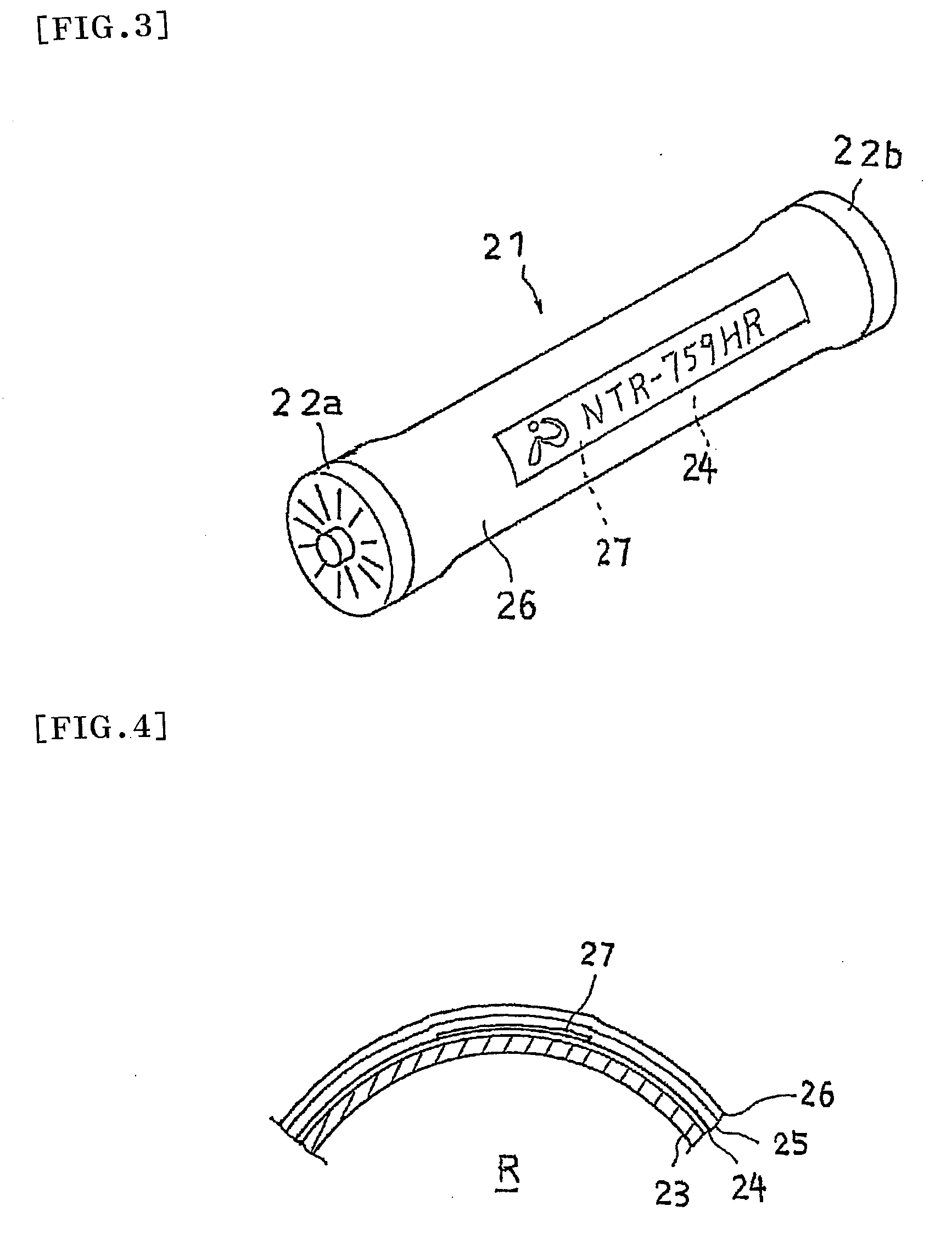
[0013]Also, it is preferable that a fiber cloth reinforcement resin layer having a fiber cloth as a reinforcing phase is interposed between the fiber reinforced plastic layer and the plastic layer. By disposing the fiber cloth reinforcement resin layer, the reinforcing effect is produced in a plurality of directions, whereby the occurrence of cracks can be more effectively prevented. Also, as shown by the result of the Examples, when compared with the case of having the same thickness, the one containing the fiber cloth reinforcement resin layer has a higher transparency of the whole outer cladding material, whereby the visibility and the recognizability in the case of disposing a display or the like on the plastic layer are improved. The details of the reasons thereof are not clear; however, it seems that, while the interference of the scattered light is liable to occur because the filaments of the fiber are arranged uniformly in parallel in the fiber roll, a fiber cloth having a variation in the arrangement or in the density of the filaments will restrain the scattered light.
[0014]Further, the fiber cloth constituting the fiber cloth reinforcement resin layer is preferably a fiber cloth having a porosity of 10% or more. This facilitates penetration of the resin to the back side of the fiber cloth to improve the adhesion between the plastic layer and the fiber cloth reinforcement resin layer, whereby the visibility and the recognizability in the case of disposing a display or the like on the plastic layer are improved to a greater extent.
[0015]Also, the outer circumferential surface of the plastic layer is preferably subjected to a surface treatment that improves the adhesion to the resin constituting the fiber cloth reinforcement resin layer. This improves the adhesion between the fiber cloth reinforcement resin layer and the plastic layer, whereby the visibility and the recognizability in the case of disposing a display or the like on the plastic layer are improved to a greater extent.

Problems solved by technology

In addition, in the case of a membrane element, unlike the general structural members, the end part cannot be largely cut and removed, so that the winding angle of the glass roving cannot be increased, and the winding angle is at most about 5°.
However, with the above method, when an increase in the scale of the display label is attempted, the effect of the unevenness of the adhesion surface of the cylindrical roll or the change in the outer diameter (the outer diameter near the end part of the membrane element increases) increases.
For this reason, the adhesion of the display label decreases, thereby raising a problem in which the display label made to have a larger scale becomes wrinkled or distorted by peeling off, distortion, or the like at the time of winding the glass roving.
On the other hand, in the case that a fiber reinforced plastic having a fiber roll as a reinforcing phase is formed as an outer cladding material like the case of using a glass roving, it will have a sufficient strength against the deformation due to the inner pressure of the membrane element but it will have a phase of being fragile against other forces, so that there are cases in which cracks occur along the fiber direction depending on the environment of use.
Also, in the case of a fiber reinforced plastic having a fiber roll as a reinforcing phase, the air layer that has penetrated between the fibers forms a communication path, whereby the barrier property of the outer cladding material tends to decrease, raising a problem of corrosion deterioration caused by penetration of chemical agents.

Method used


Image

  • Spiral membrane element
  • Spiral membrane element
  • Spiral membrane element

Examples


example 1

[0078]First, a membrane leaf unit made of an RO membrane ES20 manufactured by Nitto Denko Corporation. and a feed-side flow passageway member made of PP and having a thickness of 0.7 mm was prepared. Next, the tip end of the permeate-side flow passageway member made of PET and having a thickness of 0.3 mm was fixed to a hollow center tube made of PPE and having a diameter of 32 mm, and the membrane leaf unit was mounted on the permeate-side flow passageway member while applying a polyurethane resin at the part corresponding to the sealing part. Next, the mounted membrane leaf unit was wound while rotating the hollow center tube around the axis and applying a tension.

[0079]Next, an adhesive tape (having a width of 75 mm) was wound in a coil form without a gap to perform shape retaining, and it was covered with a tubular heat-shrinking film (made of a PP resin, having a thickness of 50 μm, a surface-treated product obtained by a corona treatment), and close adhesion was made by heatin...

example 2

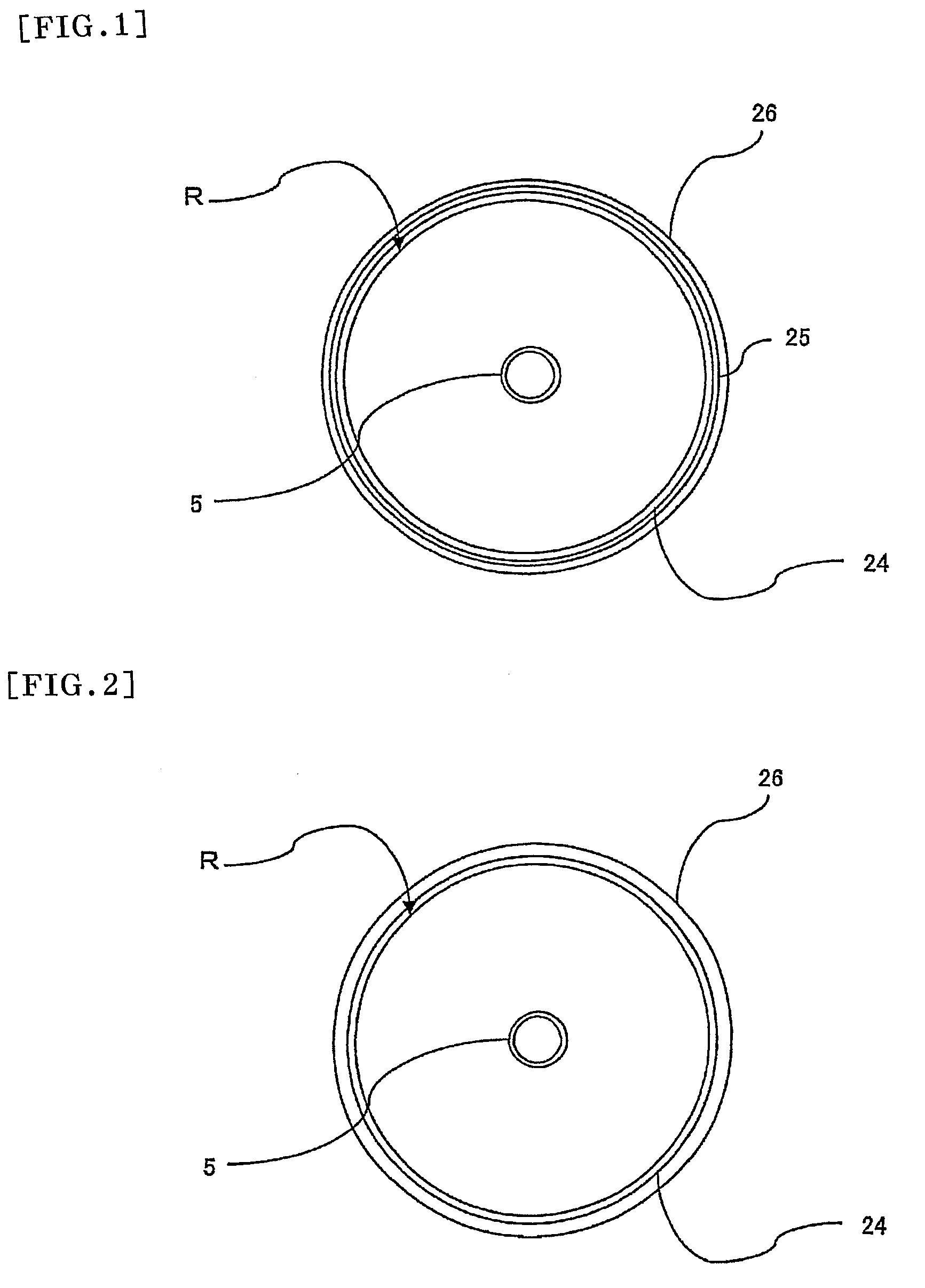
[0083]A spiral membrane element was fabricated under the same condition as in the Example 1 except that a fiber reinforcement layer having a thickness of 2 mm was disposed without disposing a fiber cloth reinforcement layer having a glass cloth as a reinforcing phase. As a result thereof, as compared with a conventional product in which the heat-shrinking film is not disposed, cracks were less liable to occur; however, the visibility and recognizability decreased as compared with the Example 1.

example 3

[0084]After performing the steps up to the sticking of a display label in a similar manner as in the Example 1, about one round of a glass cloth having a thickness of 0.15 mm (manufactured by Nitto Bouseki Co., Ltd., plain weave fabric, having a porosity of 30%) was wound as it was, and the two ends were fixed with a two-sided tape. Onto this, a glass roving impregnated with an epoxy resin (manufactured by Asahi Fiber Glass Co., Ltd.) was wound with a thickness of 1.5 mm, and the resin was hardened at 25° C. to form a fiber cloth reinforcement resin layer and a fiber reinforced plastic layer, thereby to fabricate a spiral membrane element.

[0085]As a result of this, the visibility and recognizability were further improved by penetration of the epoxy resin to the display label surface through the opening of the glass cloth, and the strength was also at a level that does not raise a problem. Also, even if the epoxy resin was not applied to the glass cloth, the resin with which the glas...


PUM

PropertyMeasurementUnit
porosityaaaaaaaaaa
winding angleaaaaaaaaaa
diameteraaaaaaaaaa

Abstract

An object of the present invention is to provide a spiral membrane element that can improve the barrier property of a fiber reinforced plastic layer having a fiber roll as a reinforcing phase and that can effectively prevent occurrence of cracks. The spiral membrane element of the present invention is a spiral membrane element containing a cylindrical roll R in which a separation membrane, a feed-side flow passageway member, and a permeate-side flow passageway member are spirally wound in a laminate state around a perforated center tube 5 and in which a sealing part for preventing mixing of feed-side fluid and permeate-side fluid is disposed, wherein a fiber reinforced plastic layer 26 having a fiber roll as a reinforcing phase is formed on the outer circumferential side of said cylindrical roll R, and a plastic layer 24 is disposed in the inner part or on the inner side of the fiber reinforced plastic layer 26 approximately over the entire length and approximately over the entire circumference of the fiber reinforced plastic layer 26.

Description

TECHNICAL FIELD[0001]The present invention relates to a spiral membrane element in which a separation membrane, a feed-side flow passageway member, and a permeate-side flow passageway member are spirally wound in a laminated state around a perforated center tube and which can separate specific components that are present in various fluids (liquid or gas).BACKGROUND ART[0002]Conventionally, as a fluid separation element used for reverse osmosis filtration, micro filtration, or the like, a spiral membrane element is known which is provided with a cylindrical roll R in which a separation membrane 1, a feed-side flow passageway member 2, and a permeate-side flow passageway member 3 are spirally wound in a laminate state around a perforated center tube 5 and in which sealing parts 11 to 13 for preventing mixing of feed-side fluid and permeate-side fluid are disposed, for example, as shown in FIG. 5.[0003]In this spiral membrane element, the feed-side fluid (feed water) is led to the sepa...

Claims


Application Information

Patent Timeline
Patent Type & Authority Applications(United States)
IPC IPC(8): B01D63/10B01D63/06B32B37/14
CPCB01D63/103B01D63/10B01D63/107B01D63/101B01D69/1213B01D69/1216B01D2325/40
Inventor ISHII, KATSUMICHIKURA, SHINICHIMATSUDA, HIDEKIBEPPU, MASASHIFUJIOKA, HIROKIUDA, YASUHIRO
Owner NITTO DENKO CORP
Learn More