Liquid-ejection head and method for manufacturing liquid-ejection head substrate

a technology of liquid injection head and substrate, which is applied in the field of liquid injection head, can solve the problems of inability to obtain the shape of the ink supply port, the shape of the bulge of the barrel shape, and the inability to reduce the size of the chips or processing in the back-end process, and achieve the effect of high manufacturing efficiency and stable manufacturing with accuracy of form

Inactive Publication Date: 2009-03-12
CANON KK
View PDF8 Cites 17 Cited by
  • Summary
  • Abstract
  • Description
  • Claims
  • Application Information

AI Technical Summary

Benefits of technology

[0012]The present invention provides a method for manufacturing a liquid-ejection head substrate, which enables l

Problems solved by technology

This is an obstacle to a reduction in size of chips or processing in a back-end process, such as a die bonding step, of chips.
However, the shapes of ink supply ports (the positions of the bulges of barrel shapes) that can be formed according to the method for forming an ink supply port having a barrel-shaped cross section, disclosed in U.S. Pat. No. 6,107,209, are limited for a processing reason.
If there is any defect in the crystal structure of a Si substrate, the state of progress of etching is changed at the defect portion, thereby making it impossible to obtain an ink supply

Method used


Image

  • Liquid-ejection head and method for manufacturing liquid-ejection head substrate
  • Liquid-ejection head and method for manufacturing liquid-ejection head substrate
  • Liquid-ejection head and method for manufacturing liquid-ejection head substrate

Examples


Embodiment Construction

[0023]An embodiment of the invention will now be described with reference to the drawings. In the following description, like reference numerals refer to like parts throughout the various views, and the explanations thereof are occasionally omitted.

[0024]Although an inkjet recording head is described as an exemplary liquid-ejection head to which the invention is applied in the following description, the scope of application of the liquid-ejection head of the invention is not limited thereto, and the invention is applicable to fabrication of biochips, printing of electronic circuits, and the like.

[0025]First, an inkjet recording head (hereinafter also referred to as a “recording head”) to which the invention is applicable is described.

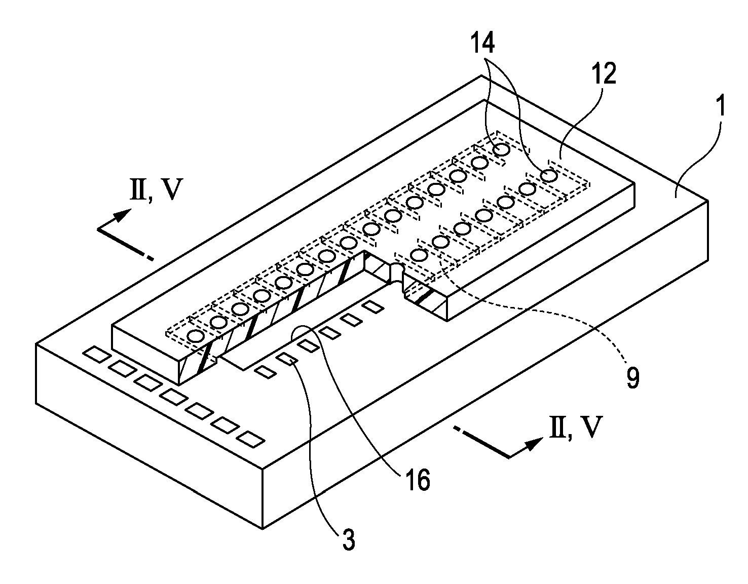
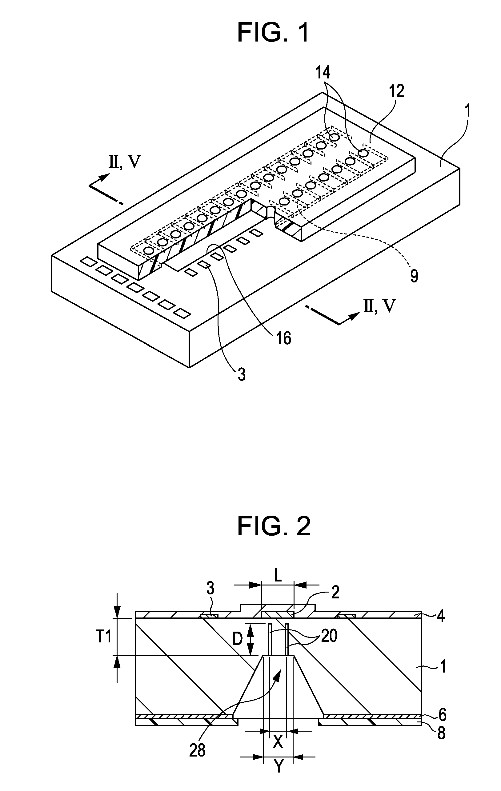
[0026]FIG. 1 is a schematic view of a recording head according to an embodiment of the invention.

[0027]The inkjet recording head has a Si substrate 1 having ink-discharging-energy generating elements 3 arranged in two lines at a predetermined pitch. A p...


PUM


Abstract

A method for manufacturing a liquid-ejection head substrate including a silicon substrate having a supply port for supplying liquid is provided. The method includes: forming an etching mask layer on a surface of the silicon substrate, the etching mask layer having an opening in a portion corresponding to the supply port; forming a first recess in the surface of the silicon substrate by anisotropically etching the silicon substrate through the opening in the etching mask layer; forming a second recess that extends toward the other surface of the silicon substrate, in a surface of the first recess in the silicon substrate; and forming the supply port by anisotropically etching the silicon substrate from the surface provided with the second recess.

Description

BACKGROUND OF THE INVENTION[0001]1. Field of the Invention[0002]The present invention relates to a liquid-ejection head for ejecting liquid, and a method for manufacturing a liquid-ejection head substrate used in a liquid-ejection head.[0003]2. Description of the Related Art[0004]An inkjet recording head used in inkjet recording is an exemplary liquid-ejection head for ejecting liquid.[0005]U.S. Pat. No. 6,143,190 discloses a method for forming, by anisotropic etching, an ink supply port that is in communication with and supplies liquid to a liquid chamber having ejection-energy generating portions for generating heat energy for jetting droplets from ejection orifices. U.S. Pat. No. 6,143,190 also discloses a method for precisely forming an ink supply port, using a sacrifice layer. U.S. Pat. No. 6,143,190 discloses the role served by the sacrifice layer during precise etching, for example, in FIGS. 1 to 3 and the description of the first embodiment related to these figures. U.S. Pat...

Claims


Application Information

Patent Timeline
IPC IPC(8): B41J2/16
CPCB41J2/14145B41J2/1603B41J2/1629B41J2/1631B41J2/1645B41J2/1634B41J2/1635B41J2/1639B41J2/1632
Inventor CHIDA, MITSURUSAKAI, TOSHIYASUOZAKI, NORIYASUABO, HIROYUKIABE, KAZUYAONO, KENJI
Owner CANON KK
Why Eureka
Try Eureka