
Nonvolatile Memory Element

a technology of nonvolatile memory and elements, applied in the field of nonvolatile memory, can solve the problems of inability to control the properties of change in the resistance of the element, the degree of change in the resistance is small, so as to achieve the effect of controlling the properties of change in the resistance and the switching properties, and improving the resistance and switching properties

Inactive Publication Date: 2009-03-12
NAT INST OF ADVANCED IND SCI & TECH
View PDF11 Cites 13 Cited by
  • Summary
  • Abstract
  • Description
  • Claims
  • Application Information

AI Technical Summary

Benefits of technology

[0021]According to the present invention, an element structure where the properties of change in the resistance and the switching properties are improved and the properties of change in the resistance can be controlled can be gained.

Problems solved by technology

In the conventional element structure, however, though nonvolatile memory effects resulting from change in the resistance can be gained, the degree of change in the resistance is small, and in addition, the switching properties are poor, and thus, the properties of change in the resistance of the element cannot be controlled.

Method used


Image

  • Nonvolatile Memory Element
  • Nonvolatile Memory Element
  • Nonvolatile Memory Element

Examples


example 1

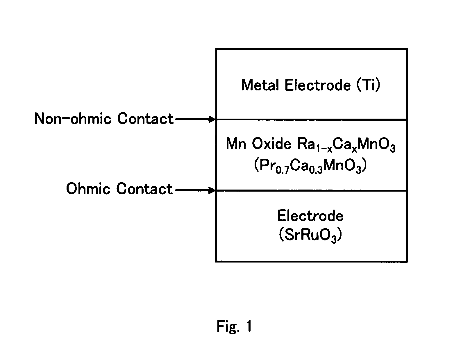
[0031]FIG. 3 is a cross sectional diagram showing the structure of a nonvolatile memory element according to Example 1 of the present invention, and the manufacturing method for the same is as follows.

[0032]A conductor having a deep work function, such as SrRuO3, having a thickness of 80 nm, which became an ohmic electrode, was formed on an SrTiO3 oxide single crystal substrate, which is an insulator, through pulse laser deposition under such conditions for fabrication that the temperature of the substrate was 700° C. and the oxygen pressure was 100 mTorr, and subsequently, Pr0.7Ca0.3MnO3 having a thickness of 100 nm, which became a p type semiconductor, was formed under the same conditions for fabrication, and then, Sm0.7Ca0.3MnO3 having a bandwidth which is smaller than that of Pr0.7Ca0.3MnO3 and insulation which is higher than that of Pr0.7Ca0.3MnO3 and having a thickness of 2 nm was formed on top of this under the same conditions for fabrication, and after that, the temperature ...

example 2

[0042]FIG. 5 is a cross sectional diagram showing the structure of a nonvolatile memory element according to Example 2 of the present invention, and the manufacturing method for the same is as follows.

[0043]A conductor having a deep work function, such as SrRuO3, having a thickness of 80 nm, which became an ohmic electrode, was formed on an SrTiO3 oxide single crystal substrate, which is an insulator, through pulse laser deposition under such conditions for fabrication that the temperature of the substrate was 700° C. and the oxygen pressure was 100 mTorr, and subsequently, La0.7Sr0.3MnO3 having a thickness of 100 nm, which became a metallic perovskite-type transition metal oxide, was formed under the same conditions for fabrication, and then, Sm0.7Ca0.3MnO3 having a bandwidth which is smaller than that of La0.7Sr0.3MnO3 and insulation which is higher than that of La0.7Sr0.3MnO3 and having the same thickness as a layer of one molecule (0.4 nm) to five molecules (2 nm) was formed on ...


PUM


Abstract

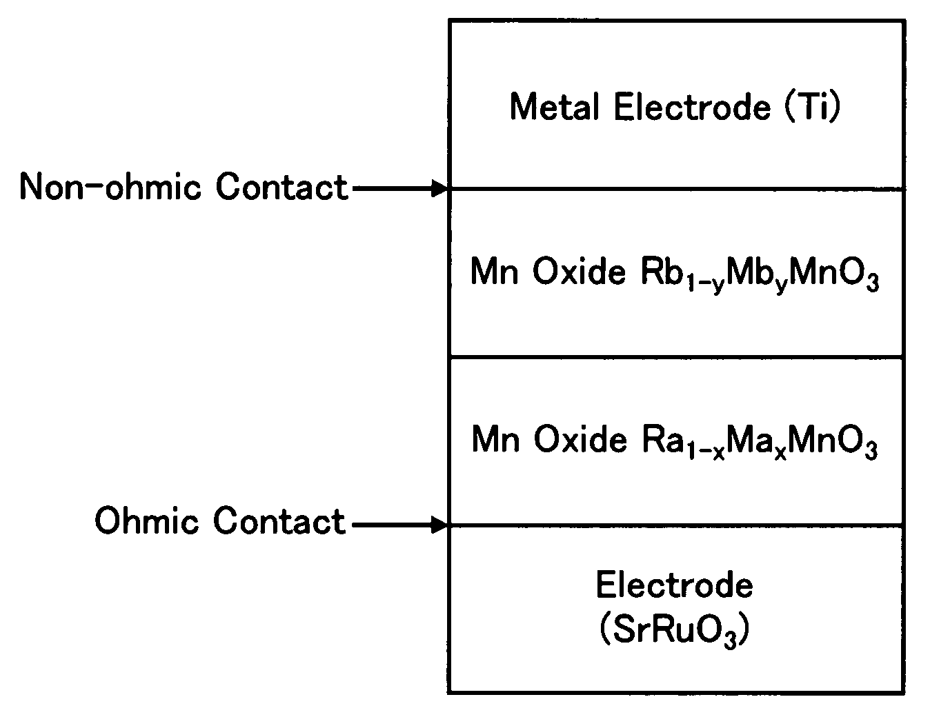
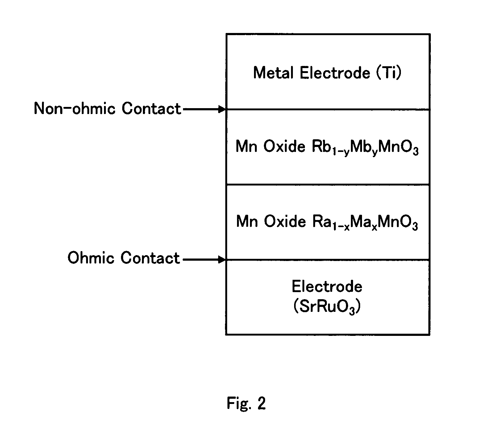
A nonvolatile memory element in which Rb1-yMbyMnO3 having higher insulation properties than Ra1-xMaxMnO3 is inserted between the Ra1-xMaxMnO3 and a metal having a shallow work function or a low electronegativity in order to improve resistance change properties and switching properties and to control the resistance change properties. (In the formulas, Ra and Rb represent rare earth elements and are solid solutions of one or more types of rare earth elements. Average ionic radius of the Rb is smaller than that of the Ra. Ma and Mb represent alkaline earth metals and are solid solutions of one or more types of alkaline earth metals. 0<x, y<1).

Description

CROSS-REFERENCE TO RELATED APPLICATIONS[0001]This application is a National Phase filing under 35 U.S.C. § 371 of International Application No. PCT / JP2006 / 305776 filed on Mar. 23, 2006, and which claims priority to Japanese Patent Application No. 2005-084926 filed on Mar. 23, 2005.TECHNICAL FIELD[0002]The present invention relates to a nonvolatile memory, and in particular, to a nonvolatile memory element using a transition metal oxide semiconductor.BACKGROUND ART[0003]Perovskite-type transition metal oxides of an intensely correlated electronic material, of which typical examples are high temperature superconductors and colossal magneto-resistance materials, have such characteristics that the electrical, magnetic and optical properties dramatically change when the charge concentration slightly changes or there is stimulation from an extremely small external field (magnetic field, electrical field, light or the like), and therefore, active research for development of elements using ...

Claims


Application Information

Patent Timeline
IPC IPC(8): H01L45/00
CPCG11C13/0007G11C2213/31G11C2213/56H01L45/1625H01L45/1233H01L45/1253H01L45/147H01L45/04H10N70/20H10N70/841H10N70/8836H10N70/826H10N70/026H01L27/105
Inventor SAWA, AKIHITOFUJII, TAKESHIKAWASAKI, MASASHITOKURA, YOSHINORI
Owner NAT INST OF ADVANCED IND SCI & TECH
Learn More