High gain planar antenna

a planar antenna, high gain technology, applied in the direction of antennas, antenna details, basic electric elements, etc., can solve the problems of only a narrow bandwidth, insufficient size of the planar antenna for some applications, and affecting the performance of the antenna, etc., to achieve high gain, small size, and easy to mak

Inactive Publication Date: 2009-03-12
LAU BILL +1
View PDF1 Cites 1 Cited by
  • Summary
  • Abstract
  • Description
  • Claims
  • Application Information

AI Technical Summary

Benefits of technology

[0005]One objective of the present invention is to provide a simple meaning to construct a planar antenna which features bo

Problems solved by technology

However, such planar antennas are not small enough for some applications, particularly as more mobile communication devices are getting smaller and smaller these days.
With these planar antennas, design effort has been ma

Method used


Image

  • High gain planar antenna
  • High gain planar antenna
  • High gain planar antenna

Examples


Embodiment Construction

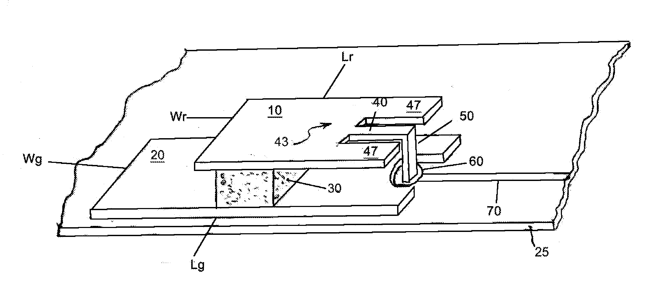
[0018]Referring to FIG. 1, it shows an exemplary planar antenna according to the present invention. The antenna includes a radiating plate 10 (also known as “radiator” or “radiated plate”) and a ground plate 20. Both the radiating plate and the ground plate are made of metal material, but other conductive materials may also provide satisfactory results. The space between the radiating plate and the ground plate is not filled with a dielectric substrate but is instead filled with an air layer. The two plates are substantially parallel with each other and are fixed on opposite sides of a dielectric support 30. The ground plate may be fixed on a dielectric substrate 25. The support serves to maintain a desired distance between the radiating plate and the ground plate and keep them substantially parallel to each other. The support can be made of any non-conducting materials, such as, for example, a cellular foam material e.g., ethylene vinyl acetate (EVA).

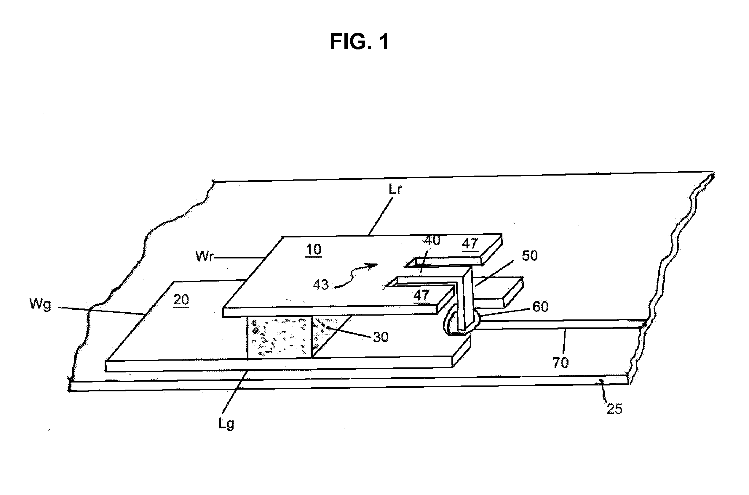
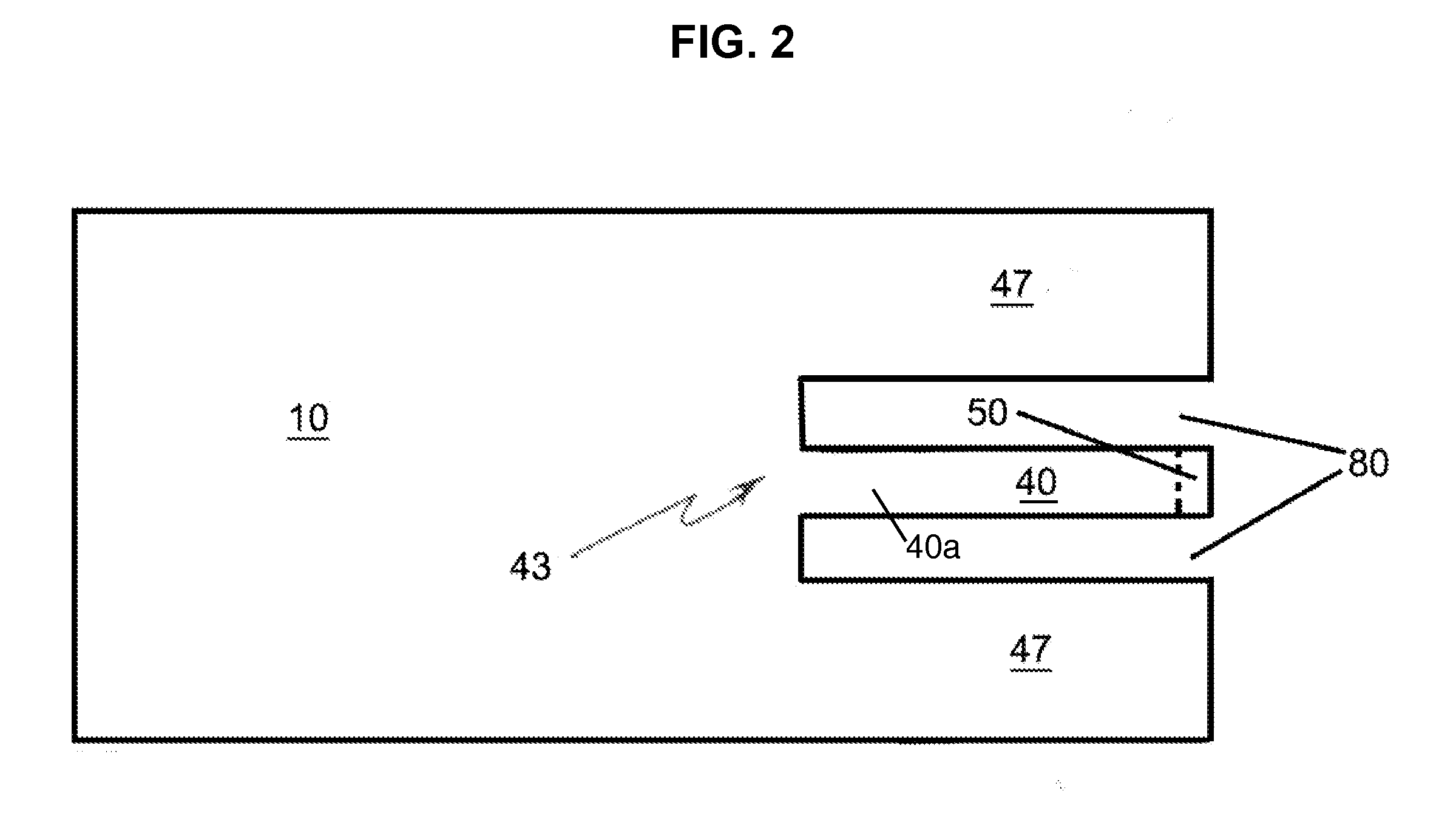
[0019]At one end of the radiati...


PUM


Abstract

A planar antenna including a radiating plate, a ground plate and a support with the radiating plate being dimensioned according to the formula L>L/2>W, where L and W are the length and width of said radiating plate, respectively. The support serves to maintain the radiating plate and the ground plate at a certain distance from each other in a substantially parallel orientation. The length of the radiating plate is approximately half of the wavelength at the operating frequency of the antenna. An air layer substrate fills in the space between the radiating plate and the ground plate. The foregoing configuration help produce an antenna with small size and high gain suitable for communication devices requiring narrow bandwidth.

Description

CROSS REFERENCE TO RELATED APPLICATIONS[0001]This application claims priority to U.S. Provisional Patent Application No. 60 / 971,010, filed Sep. 10, 2007, the contents of which are hereby incorporated by reference.FIELD OF THE INVENTION[0002]This invention relates to a planar antenna used for transmitting and receiving electromagnetic signals. Particularly, it relates to a planar antenna with novel configurations of a radiating plate and a ground plate to achieve high gain, small size and easy impedance matching and band pass filtering.BACKGROUND OF THE INVENTION[0003]Planar antennas are well known in the art. Referring to FIG. 5, a typical such antenna, usually with a low profile, may include a planar conductive radiating plate 127, and planar conductive ground plate or ground plate 102. The two plates 127 and 102 are in general parallel to each other. Conventionally, such planar antenna employs a probe pin 108 as the feeding meaning and the two plates are usually separated by an ai...

Claims


Application Information

Patent Timeline
IPC IPC(8): H01Q1/38
CPCH01Q9/0407H01Q1/243
Inventor LAU, BILLLAU, EDDIE
Owner LAU BILL
Why Eureka
Try Eureka