Patient Positioner System

a patient positioner and patient technology, applied in the field of robotics, can solve the problems of limited patient positioning envelope, and inability to provide vertical movement in direct perpendicular path relative to the floor, so as to reduce the overall capital cost of treatment facilities, reduce operational costs, and increase patient throughput

Active Publication Date: 2009-03-19
LUZADER DAVID J +2
View PDF33 Cites 63 Cited by
  • Summary
  • Abstract
  • Description
  • Claims
  • Application Information

AI Technical Summary

Benefits of technology

[0012]The present invention provides an improved patient positioner system for radiotherapy and other medical applications. The present invention features a patient positioning robot under computer control that is designed and controlled in manner so as to reduce overall treatment facility capital costs, increase patient throughput, thereby reducing operational costs, while simultaneously increasing patient and treatment facility operator safety.

Problems solved by technology

Unfortunately, this arrangement provides an envelope in which the patient table may be positioned that has voids.
However, in this robotic system the vertical movement is not provided in a direct perpendicular path relative the floor.
Further, due to the lack of a direct linear vertical positioning component, the envelope for positioning the patient is limited.
This arrangement provides for numerous dead spots within the envelope for positioning the patient relative to the particle emitter therefore limiting the effectiveness of the patient positioner system.
The use of robots for patient positioning in medical treatment and similar settings poses both opportunities for increased patient treatment efficiency (and therefore lower cost) and effectiveness, and challenges for patient and medical personnel safety.
Radiotherapy operations, such as proton beam treatment, can be very expensive, both in the capital cost involved in setting up such a facility and the operational costs associated with facility operations.
However, such increased efficiency can not be obtained at the cost of reduced treatment effectiveness or of reduced safety to the patient or to medical personnel providing such treatment.

Method used


Image

  • Patient Positioner System
  • Patient Positioner System
  • Patient Positioner System

Examples


Embodiment Construction

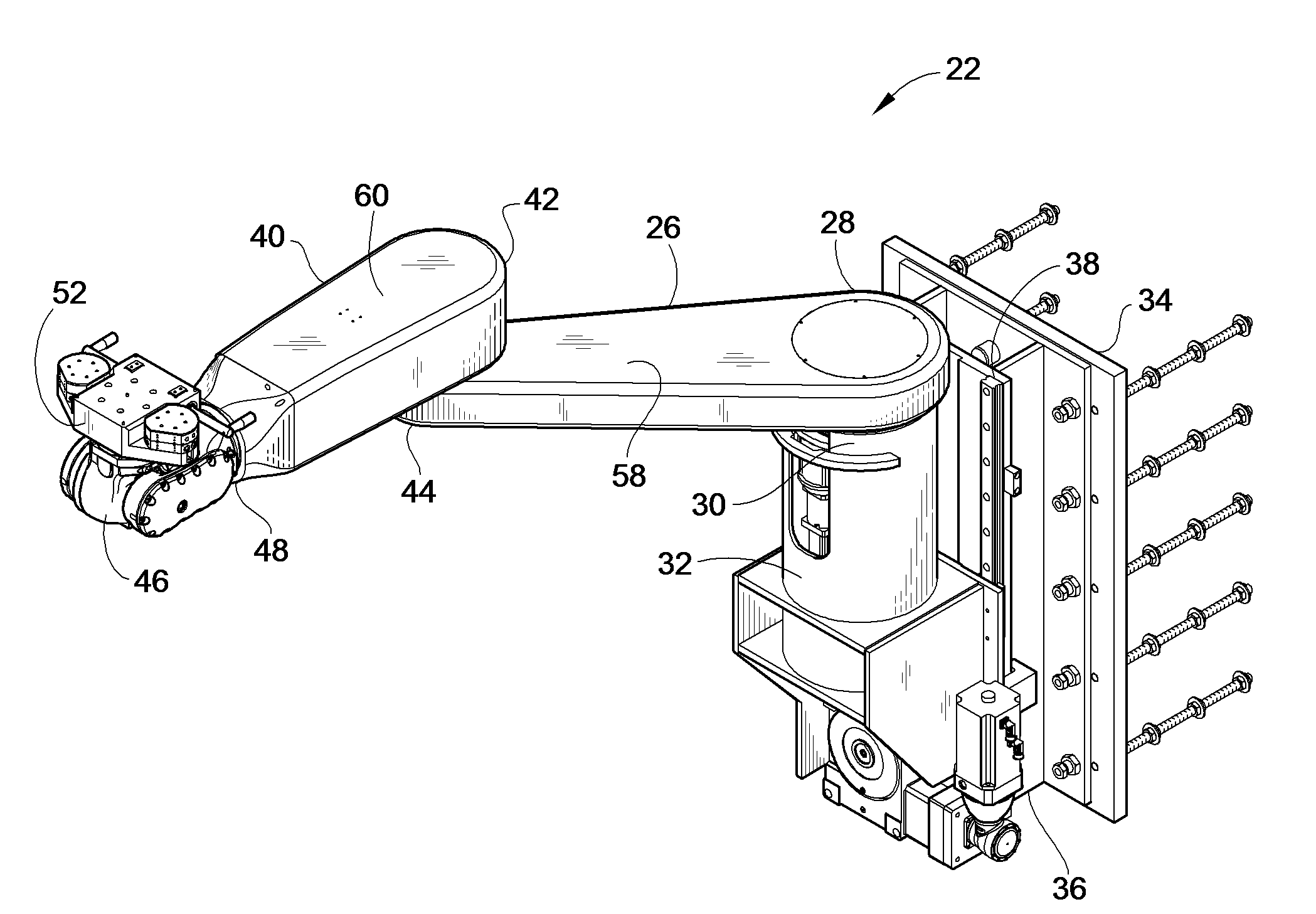
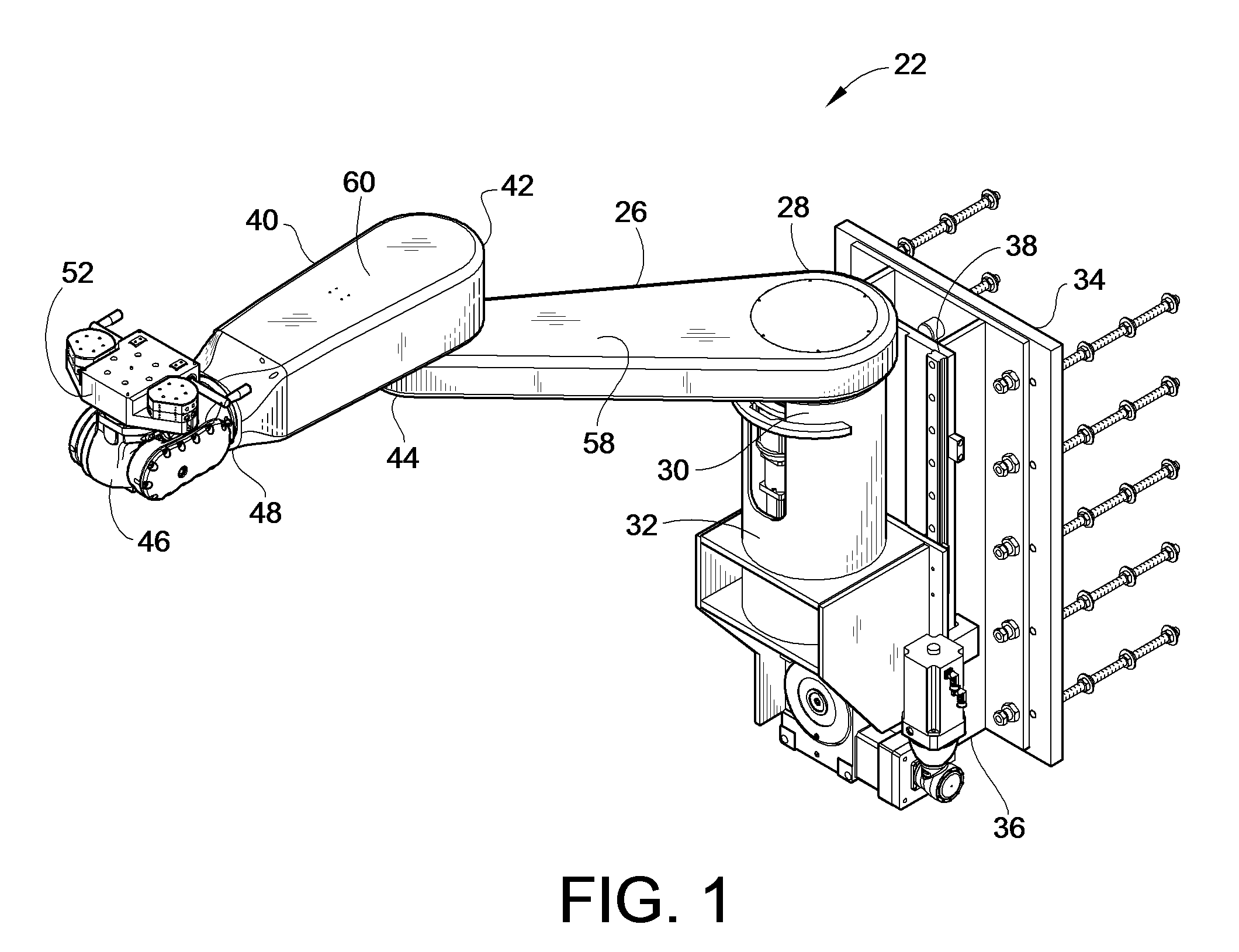
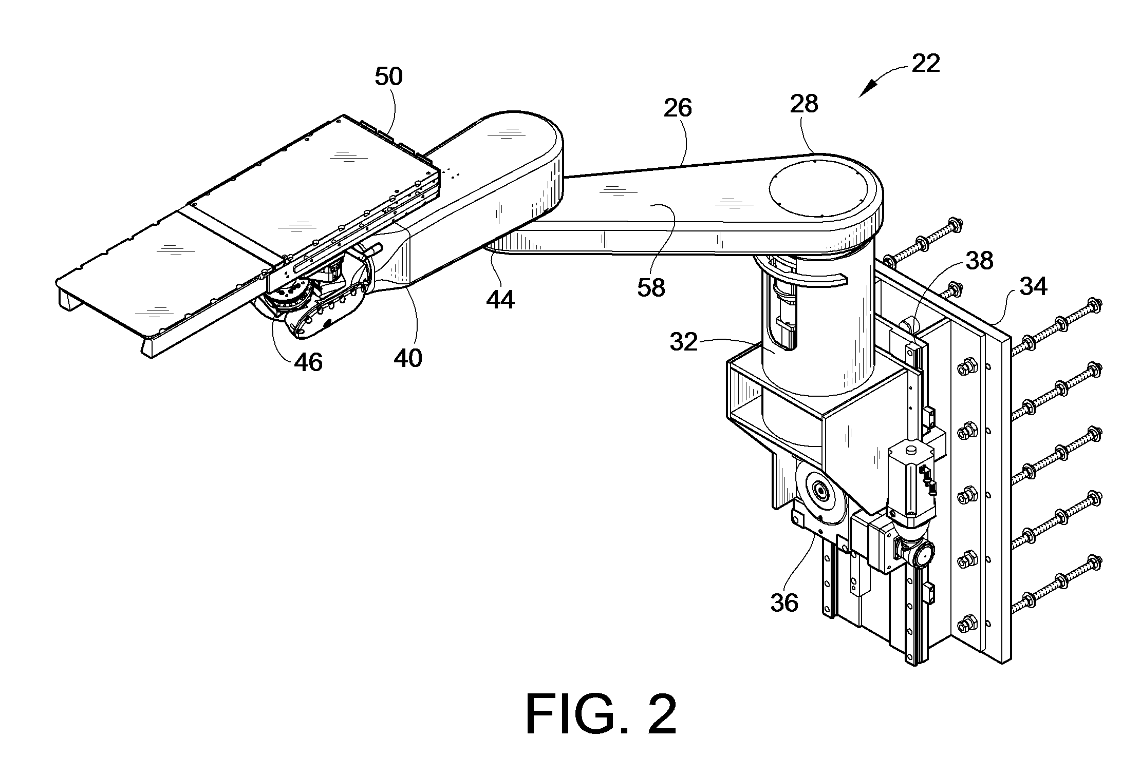
[0040]The present invention will now be described in detail with reference to the particular application of a patient positioner system for use in positioning a human patient for radiotherapy treatment, such as in a proton beam treatment room or facility. It should be understood, however, the present invention may also have application in other types of treatments or other medical procedures, including diagnostic procedures and major surgery, for both humans and animals. Furthermore, it should be understood that features of the present invention may also find application entirely outside of the medical field, such as in an industrial, manufacturing, or scientific research setting.

[0041]A complete patient positioner system 20 in accordance with the present invention includes a robot 22 (See FIG. 1) and a control system 24 (See FIG. 7) therefore. Unless otherwise described herein, conventional robot parts, assembly methods, hardware, software, safety and control circuitry as are known...


PUM


Abstract

A computer controlled robot system for positioning a patient for radiation therapy or other medical procedures and the like. The robot is mounted at the top of a vertical shaft extending from the treatment room floor and includes horizontal arms arranged to maximize the available work envelope and eliminate “dead spots” in the envelope that the robot cannot reach. A double redundant coupling system for coupling devices to the robot is provided. A vision based docking system is employed for automatically coupling devices to the robot. Various enhanced safety features are provided, including device specific collision avoidance.

Description

CROSS-REFERENCE TO RELATED PATENT APPLICATIONS[0001]This patent application claims the benefit of U.S. Provisional Patent Application No. 60 / 972,107, filed Sep. 13, 2007, the teaching and disclosure of which are hereby incorporated in their entireties by reference thereto.FIELD OF THE INVENTION[0002]This invention pertains generally to robotics and more particularly to robotic systems for positioning patients for medical procedures.BACKGROUND OF THE INVENTION[0003]Robots used in industrial manufacturing applications are well known. Such robots are designed and programmed to perform specific functions repeatedly and precisely. Thus, robots are often used in such applications to perform operations, such as assembly in an assembly line setting, more efficiently, and often producing higher and more consistent quality, than such operations could be performed by humans.[0004]Conventional industrial robots typically have one or two robotic arms. These robotic arms can have multiple segment...

Claims


Application Information

Patent Timeline
Patent Type & Authority Applications(United States)
IPC IPC(8): A61B6/04
CPCA61B6/0457B25J9/042A61N2005/1087A61N5/1049A61B6/0487A61B34/30A61B2090/064A61G13/02A61G13/104A61G2203/30A61G2203/32A61G2210/50B25J15/0019B25J15/04B25J19/066Y10S901/02Y10S901/09Y10S901/11B25J9/1671B25J9/1674B25J9/1676B25J9/1689
Inventor HENDERSON, TOBY D.SCHREUDER, NIEKBRODERICK, BRIAN
Owner LUZADER DAVID J
Why Eureka
Try Eureka