Sealing structure for high-pressure container
- Summary
- Abstract
- Description
- Claims
- Application Information
AI Technical Summary
Benefits of technology
Problems solved by technology
Method used
Image

Examples
first embodiment
[0028]An exemplary structure of a high-pressure container to which a first embodiment is applied will be described below, followed by a description of sealing structures for a high-pressure container according to the first embodiment.
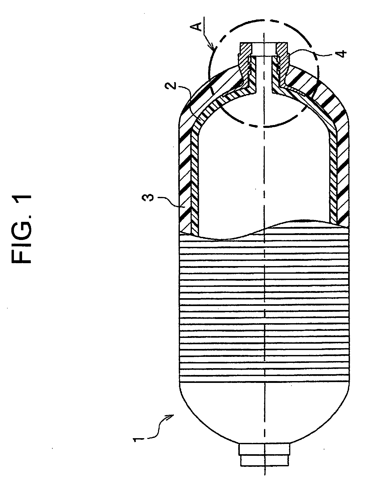
[0029]FIG. 1 is a side view and partial sectional view of the high-pressure container. The high-pressure container 1 includes a resin liner 2 used to contain gas or liquid, a fiber-reinforced plastic layer 3 used to reinforce an outside face of the resin liner 2, and a mouthpiece 4 used to pour and discharge the gas or liquid, protruding outside the fiber-reinforced plastic layer 3.
[0030]The resin liner 2, which is used to contain gas or liquid, has its material selected according to a substance to be contained and filling conditions. Available materials include, for example, high density polyethylene (HDPE), polyamide, polyketone, and polyphenylene sulfide (PPS). The resin liner 2 is formed by rotational molding, blow molding, or the like.
[0031]The pre...
second embodiment
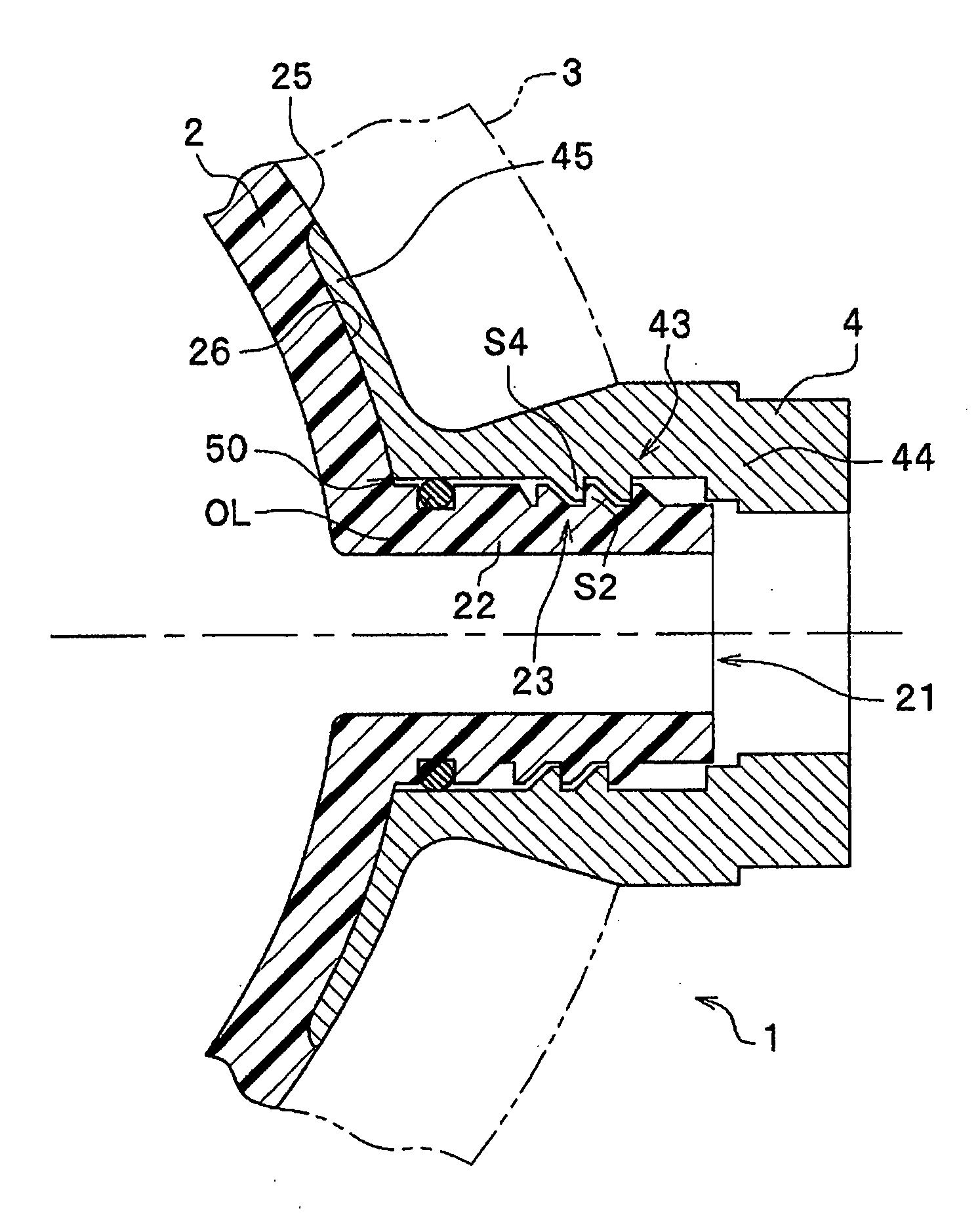
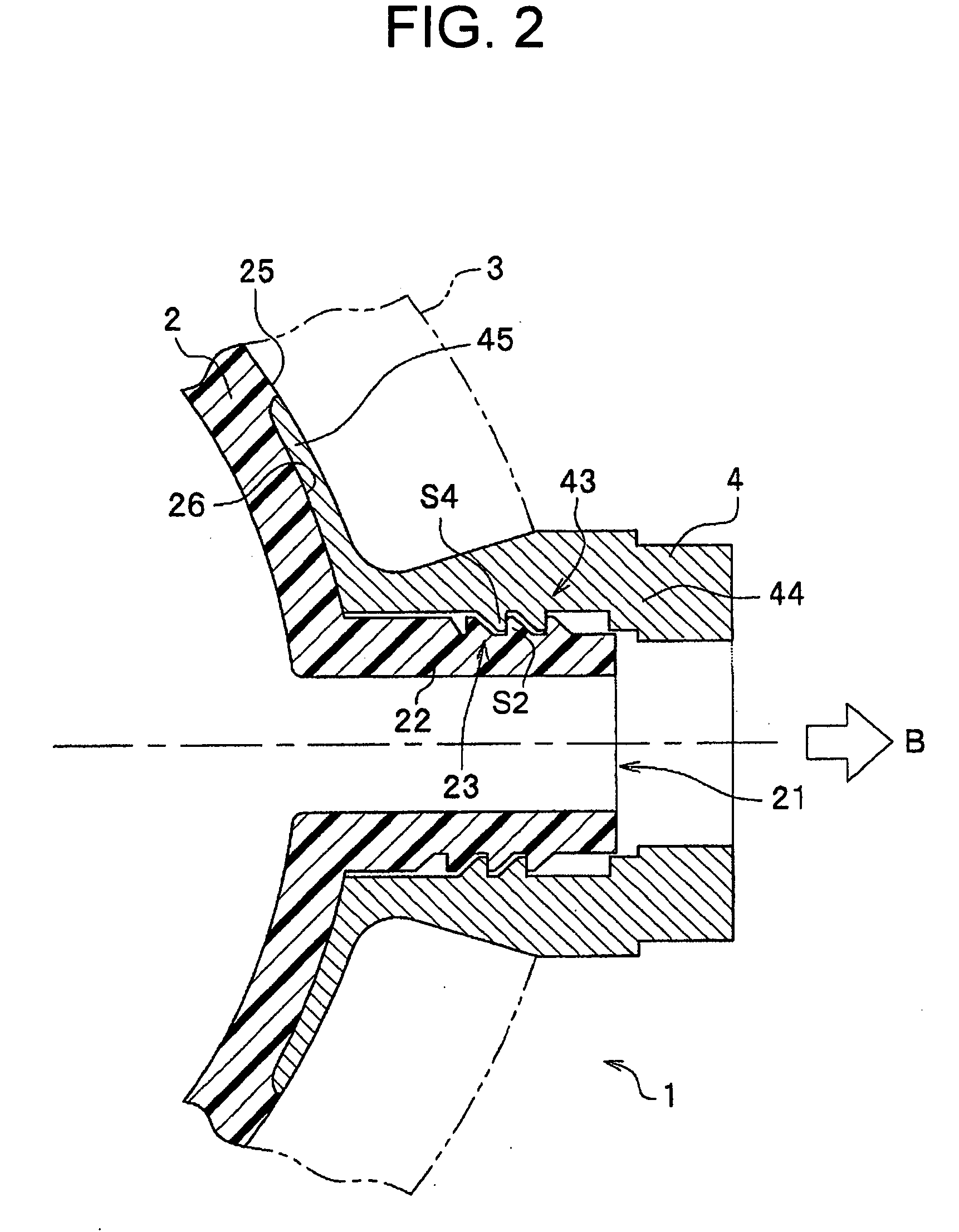
[0047]Next, a sealing structure for a high-pressure container according to a second embodiment will be described with reference to FIG. 3. FIG. 3 is a detailed view of part A in FIG. 1, showing coupling structures of the resin liner 2 and mouthpiece 4.
[0048]The present embodiment differs from the first embodiment in that an O-ring OL is installed near a corner 50 as a sealing member for an abutting portion between the resin liner 2 and mouthpiece 4, where the abutting portion could become a potential leak path. In this area, a potential leak path is closed off by self-sealing under pressure loading as described in the first embodiment, and the use of the O-ring OL increases the sealing effect by covering a root of the neck uniformly by elastic deformation.
[0049]Furthermore, even if a root of the protrusion 22 on the resin liner 2 is deformed by internal pressure exerted on the high-pressure container 1 filled with gas or liquid, the O-ring OL absorbs the deformation, provided that t...
third embodiment
[0052]Next, a sealing structure for a high-pressure container according to a third embodiment will be described with reference to FIGS. 4A and 4B. FIG. 4A is an enlarged front view showing coupling structures of a resin liner 102 and mouthpiece 104 as viewed from the right in FIG. 2 while FIG. 4B is an enlarged exploded perspective view showing the coupling structure 123 of the resin liner 102 as viewed from a side.
[0053]The present embodiment differs from the first embodiment in that clearances G which open to the outside of the container are formed between the mouthpiece 104 and the coupling structure 123 of the resin liner 102 when the mouthpiece 104 and resin liner 102 are coupled and that a sealing member can be inserted in the clearances G.
[0054]Specifically, according to the present embodiment, as in the case of the first embodiment, threads 1S2 cut in the filler neck 121 are screwed into threads 1S4 cut in a coupling structure 143 of the mouthpiece 104 to couple the resin li...
PUM
| Property | Measurement | Unit |
|---|---|---|
| Pressure | aaaaa | aaaaa |
Abstract
Description
Claims
Application Information
 - R&D
- Intellectual Property
- Life Sciences
- Materials
- Tech Scout
- Unparalleled Data Quality
- Higher Quality Content
- 60% Fewer Hallucinations
Browse by: Latest US Patents, China's latest patents, Technical Efficacy Thesaurus, Application Domain, Technology Topic, Popular Technical Reports.
© 2025 PatSnap. All rights reserved.Legal|Privacy policy|Modern Slavery Act Transparency Statement|Sitemap|About US| Contact US: help@patsnap.com