
High Altitude Airship Configuration And Power Technology And Method For Operation Of Same

Active Publication Date: 2009-03-19
UNITED STATES OF AMERICA REPRESENTED BY SEC OF THE NAVY +1
View PDF7 Cites 46 Cited by
  • Summary
  • Abstract
  • Description
  • Claims
  • Application Information

AI Technical Summary

Benefits of technology

[0006]Accordingly, it is an object of the present invention to provide a thermoelectric energy conversion system that is lighter than many known systems.
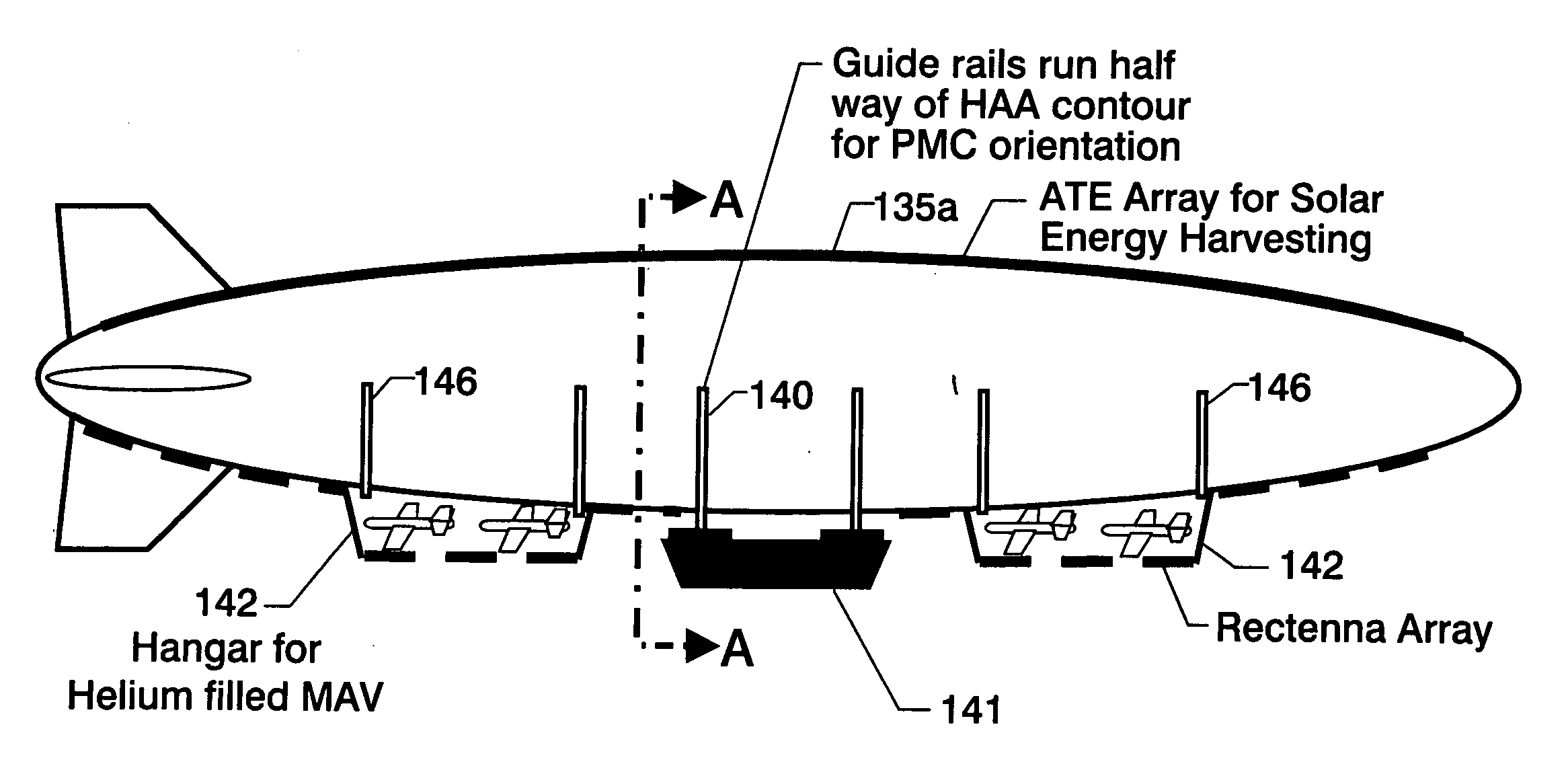
[0011]Another object of the present invention is to provide an HAA configured and powered to permit long term operation.
[0013]In accordance with the present invention, these objects and their attending benefits are achieved by providing an airship having an elliptical cross-section, utilizing advanced thermoelectric technology for converting solar energy incident thereon, and which airship is configured and operated in a manner to maximize the collection of such solar energy. The advanced thermoelectric technology comprising a plurality of thermoelectric layers in a tandem mode, each layer being suited for best performance within a particular temperature range, and at least one of these layers comprises an advanced thermoelectric material, and whereby these layers provide a cascaded efficiency.

Problems solved by technology

Such a scenario of HAA applications requires a substantial amount of power to operate surveillance systems, probes, sensors, telescopes, radar systems, etc.
The propulsion and maneuverability of HAAs also requires a significant amount of power.
The weight growth of HAA is limited by the long-term operation requirements and the limit on weight growth (possible lighter than air requirement).
Accordingly, it can offer no room for fuel-carrying power generators which limit the operational time or otherwise increase the overall weight.
However, the cost, weight and photon energy coupled band-gap energy structure of high efficiency photovoltaic cells pose shortcomings for wide and unlimited applications.
Thus, many potential solar power applications, including airships, can find photovoltaic cells and fuel cells difficult, or impossible, to use.

Method used


Image

  • High Altitude Airship Configuration And Power Technology And Method For Operation Of Same
  • High Altitude Airship Configuration And Power Technology And Method For Operation Of Same
  • High Altitude Airship Configuration And Power Technology And Method For Operation Of Same

Examples


Embodiment Construction

should be read together with the accompanying drawings, wherein:

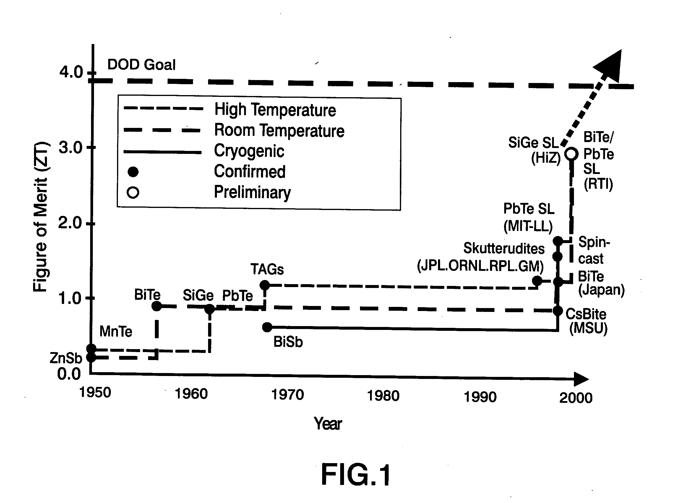
[0015]FIG. 1 is a graph depicting the History of Thermoelectric Figure of Merit (ZT);

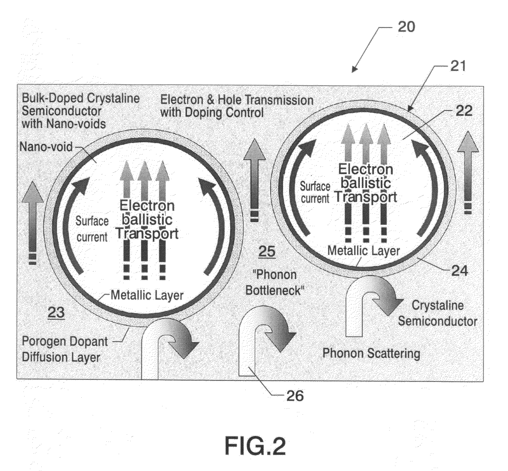
[0016]FIG. 2 is an illustration of a morphological design of an advanced thermoelectric material to enhance the ZT by increasing electrical conductivity while suppressing thermal conductivity by populating nanovoids into the material, which material can be utilized in at least one embodiment of the present invention;

[0017]FIG. 3 is a graph of the figure of merit of several TE materials which could be utilized in at least one embodiment of the present invention;

[0018]FIG. 4 is a flow chart of the fabrication of a nanovoid bismuth telluride (Bi—Te) thermoelectric material that could be utilized in at least one embodiment of the present invention;

[0019]FIG. 5 is a diagram depicting a portion of the fabrication process of the Bi—Te thermoelectric material referenced in FIG. 4, i.e., the formation of low-dimensional bismuth telluride nanocry...


PUM


Abstract

A new High Altitude Airship (HAA) capable of various extended applications and mission scenarios utilizing inventive onboard energy harvesting and power distribution systems. The power technology comprises an advanced thermoelectric (ATE) thermal energy conversion system. The high efficiency of multiple stages of ATE materials in a tandem mode, each suited for best performance within a particular temperature range, permits the ATE system to generate a high quantity of harvested energy for the extended mission scenarios. When the figure of merit 5 is considered, the cascaded efficiency of the three-stage ATE system approaches an efficiency greater than 60 percent.

Description

ORIGIN OF THE INVENTION [0001]This invention was made in part by employees of the United States Government and may be manufactured and used by or for the Government of the United States of America for governmental purposes without the payment of any royalties thereon or therefor.BACKGROUND OF THE INVENTION [0002]Pursuant to 35 U.S.C. §119, the benefit of priority from provisional application 60 / 834,547, with a filing date of Jul. 31, 2006, is claimed for this non-provisional application.FIELD OF THE INVENTION [0003]This invention generally relates to high altitude airship (HAA) configurations and operation. More specifically, the invention comprises new advanced thermoelectric (ATE) power technology, and new HAA configurations and methods for operation utilizing this new power technology.DESCRIPTION OF THE RELATED ART [0004]The applications and uses of HAAs are extensive and might include earth surveillance, such as for scientific and weather monitoring. Commercial applications incl...

Claims


Application Information

Patent Timeline
IPC IPC(8): B64B1/06H01L35/02H01L35/34
CPCB64B1/06B64B1/20B64B1/30B64C2201/022B64C2201/042H01L35/26B64C2201/125B64C2201/127H01L35/16H01L35/22B64C2201/122B64U10/30B64U2101/35B64U50/19B64U2101/30H10N10/857H10N10/855H10N10/852B64U2101/23B64U50/31B64U2101/20
Inventor CHOI, SANG H.ELLIOTT, JR., JAMES R.KING, GLEN C.PARK, YEONJOONKIM, JAE-WOOCHU, SANG-HYON
Owner UNITED STATES OF AMERICA REPRESENTED BY SEC OF THE NAVY
Learn More