Method for producing nanocarbon and catalytic reaction device for producing nanocarbon

a catalyst and nano-carbon technology, applied in the direction of chemical/physical/physical-chemical processes, physical/chemical process catalysts, chemical apparatus and processes, etc., can solve the problems of deterioration of reaction efficiency and energy efficiency, disadvantage of continuous reaction, and cost addition, and achieve the effect of reducing the number of catalyst particles in the bed, reducing the number of catalyst particles, and improving the efficiency of reaction efficiency

Active Publication Date: 2009-03-19
KITAMI INST OF TECH +2
View PDF8 Cites 37 Cited by
  • Summary
  • Abstract
  • Description
  • Claims
  • Application Information

AI Technical Summary

Benefits of technology

[0024]As mentioned above, the method for producing nanocarbon of the invention comprises continuously feeding a low hydrocarbon and a catalyst through a screw feeder in such a manner that the two components are brought into contact with each other in a forward current or counter flow so that the low hydrocarbon is pyrolyzed over the catalyst in the screw feeder to produce a composite of nanocarbon while continuously conveying the composite of nanocarbon formed on the catalyst by pyrolysis and the catalyst by the screw toward the downstream side of the screw feeder from which it is then discharged out of the screw feeder, whereby nanocarbon which has grown with the catalyst as top with time can be continuously discharged out of the reaction pipe while unused catalyst is being fed to the screw feeder at the same amount as that of nanocarbon, allowing efficient continuous reaction.
[0025]In the present reaction, the portion which is taken into the surface of the catalyst or grown carbon to take part in the reaction decreases with time or depending on the reaction conditions, making it difficult for the catalytic reaction to proceed. In the invention, however, a two-faced catalyst / product which is a material that can difficultly cause reaction as a catalyst but is a completed nanocarbon product is withdrawn from the reactor while replenishing with unused catalyst, making it possible to keep conversion of low hydrocarbon at the inlet and outlet of the reactor constant.
[0026]Further, the nanocarbon producing reactor of the invention a cylindrical screw feeder main body as a pressure reaction vessel, a catalyst feeding portion for introducing a catalyst into the screw feeder main body, a low hydrocarbon feeding portion for introducing a low hydrocarbon into the screw feeder main body as a raw material, one or a plurality of screws rotatably disposed in the screw feeder main body for conveying the catalyst and nanocarbon produced by pyrolysis of the low hydrocarbon in the feeder main body, a solid matter discharging portion disposed in the screw feeder main body for discharging the catalyst and the nanocarbon conveyed by the screw out of the screw feeder main body and a gas discharging portion disposed in the screw feeder main body for discharging the unreacted low hydrocarbon and hydrogen produced by the pyrolysis of the low hydrocarbon out of the screw feeder main body, whereby the aforementioned effect can be certainly exerted and a compact device can be designed to provide an inexpensive device.

Problems solved by technology

Therefore, when the fixed bed process is used in the present process, the reaction space is gradually filled with and blocked by grown carbon, preventing the raw material gas from flowing therethrough and hence disabling continuous reaction to disadvantage.
However, the application of ordinary moving bed process to the present process, which involves endothermic reaction, results in the deterioration of reaction efficiency and energy efficiency that adds to cost.
In the present process, however, the volume and weight of catalyst change with time, making it difficult to control the distribution of particle size of catalyst in the bed.
However, the present process reaction doesn't proceed so fast.
Further, the fluidized bed requires a large-sized apparatus that adds to construction cost.

Method used


Image

  • Method for producing nanocarbon and catalytic reaction device for producing nanocarbon
  • Method for producing nanocarbon and catalytic reaction device for producing nanocarbon
  • Method for producing nanocarbon and catalytic reaction device for producing nanocarbon

Examples


example

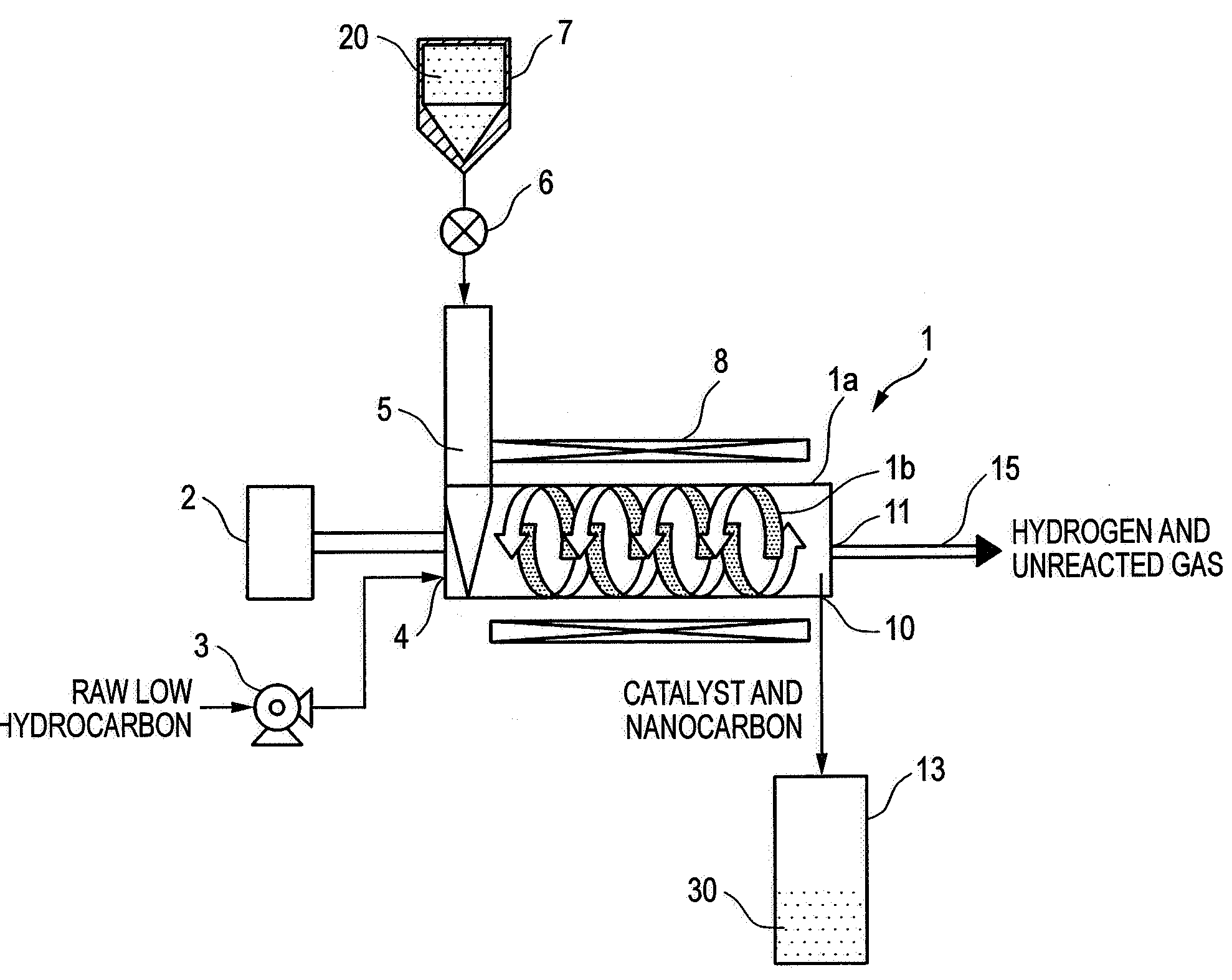
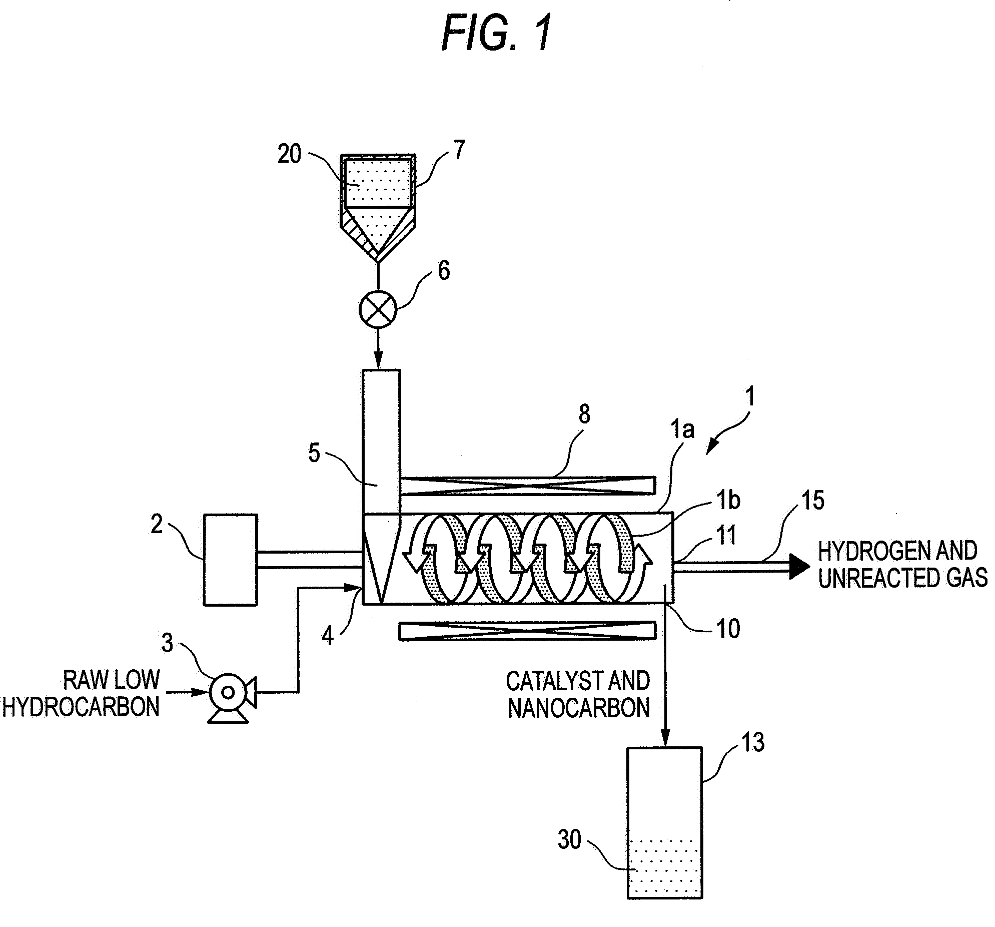
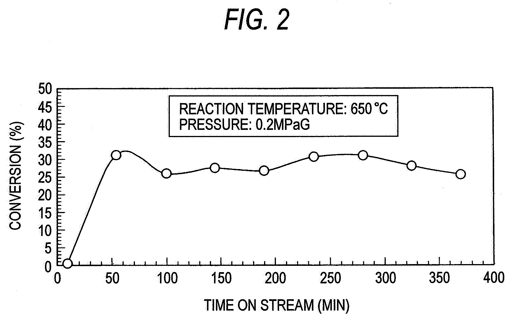
[0053]An example of reformation of methane using the screw feeder type catalytic reactor shown in FIG. 1 will be described below. In the present example, the temperature and pressure in the screw feeder main body were adjusted to 650° C. and 0.2 MPaG, respectively, and the flow rate of methane was predetermined to about 3,000 ml / g-Ni / h as calculated in terms of SV value.

[0054]The relationship between the time on stream of operation and the conversion is shown in FIG. 2. In general, the catalytic properties deteriorate with time. In the present example, however, the conversion remains constant because unused catalyst is continuously fed. It was also made obvious that unused catalyst is fed at a constant rate by a screw feeder while the resulting nanocarbon is being extruded without clogging the feeder, allowing continuous progress of reaction without clogging the reaction pipe.

[0055]FIG. 3 is a SEM photograph of nanocarbon produced by the reaction. This SEM photograph demonstrates th...


PUM

PropertyMeasurementUnit
pressureaaaaaaaaaa
temperatureaaaaaaaaaa
diameteraaaaaaaaaa

Abstract

A cylindrical screw feeder main body, catalyst feeding portions for introducing a catalyst into the screw feeder main body, low hydrocarbon feeding portions for introducing a low hydrocarbon into the screw feeder main body as a raw material, a screw for conveying the catalyst and nanocarbon produced by pyrolysis of the low hydrocarbon in the feeder main body, a solid matter discharging portion for discharging the catalyst and the nanocarbon conveyed by the screw out of the screw feeder main body and a gas discharging portion for discharging the unreacted low hydrocarbon and hydrogen produced by the pyrolysis of the low hydrocarbon out of the screw feeder main body are provided. Nanocarbon grown with the catalyst as top with time is continuously discharged out of the screw feeder main body while unused catalyst is being fed thereto at the same amount as that of nanocarbon, allowing efficient continuous reaction.

Description

CROSS-REFERENCE TO RELATED APPLICATIONS[0001]This application is a Divisional of U.S. patent application Ser. No. 11 / 378,363, which claims benefit of Japanese Patent Application No. 2005-114302. The above-noted applications are incorporated herein by reference in their entirety.BACKGROUND OF THE INVENTION[0002]1. Field of the Invention[0003]The present invention relates to a method for the production of nanocarbon which comprises subjecting a low hydrocarbon such as methane as a raw material to catalytic reaction so that the raw material is directly decomposed to produce nanocarbon and hydrogen and a catalytic reaction device for producing nanocarbon.[0004]2. Description of the Related Art[0005]As a device for producing nanocarbon from a low hydrocarbon as a raw material there has been heretofore known a carbon dioxide fixing device as disclosed in JP-A-10-182121. This fixing device is intended to fix mainly carbon dioxide using methane and carbon dioxide as raw material. This fixin...

Claims


Application Information

Patent Timeline
Patent Type & Authority Applications(United States)
IPC IPC(8): B01J19/00
CPCB01J6/008B01J8/10B01J35/02Y10S977/842C01B31/02Y10S977/843B82Y30/00C01B3/26C01B2203/04C01B2203/1047C01B2203/1058C01B32/05C01B32/15C01B32/164B01J2208/00867B01J19/20
Inventor TADA, AKIONAKAMURA, SATORUNAKAMURA, TETSUNARIKAKIHARA, HAJIMETOGO, YOSHITAKAKOSEKI, KIKUOTAKASUNA, HIROYUKI
Owner KITAMI INST OF TECH
Why Eureka
Try Eureka