
Hybrid fabric

a fabric and hybrid technology, applied in the field of spacer fabric, can solve the problems of difficult control of mechanical and thermo-molding properties of crimped fibers, and loss of porosity of fabric,

Active Publication Date: 2009-03-19
ORFIT IND
View PDF8 Cites 12 Cited by
  • Summary
  • Abstract
  • Description
  • Claims
  • Application Information

AI Technical Summary

Benefits of technology

[0002]In order to be suitable for use in immobilization devices for supporting, stabilizing or immobilizing a limb, joint, muscle, bone or other body part, a material should meet certain requirements. On the one hand the material must be sufficiently rigid, resistant to impact and compression in order to provide good immobilization and minimize the possibility of the body part enclosed by it, to move. In specific applications, such as fractionated medical diagnostic and treatment procedures, for example in radiation oncology, accurate and reproducible positioning and re-positioning of the body part are a pre-requisite to ensure that the radiation is delivered exactly at the target position where it is needed, while minimizing the risk to exposure of surrounding healthy tissue. On the other hand the material should be light and comfortable to wear, be skin friendly, provide cushioning and show some breathability to permit air and moisture transport from the skin through the material to improve comfort to the patient and minimize the risk to skin damaging or wounding. Improved comfort may be obtained by using a perforated material or by covering the inner face of a rigid brace with textile to improve the wearing comfort to the patient, provide cushioning, softness, skin friendliness, moisture handling and breathability. Furthermore, it is important that the material for the immobilization device has a sufficiently high melt strength to permit molding in the molten state, that it is sufficiently elastic and flexible during molding in order to achieve a good fit for a wider range of body sizes and shapes, and at the same time provide the right amount of support and compression.

Problems solved by technology

Upon subsequent cooling a matrix of thermoplastic material is formed which stiffens the surface of the spacer fabric and entails a loss of the porosity of the fabric.
Besides this, the behavior of hybrid fibers during subsequent shaping and use, the adhesion of the thermoplastic fiber to the structural fiber and the mechanical and thermo-molding properties of the crimped fibers have been found difficult to control.
However, the flowing of the thermoplastic material causes matrix formation to occur, gaps present in the fabric are closed and the porosity and breathability of the material is lost.
The material may be shaped by means of thermo-shaping, molding, heat setting, shrinking, shaping on / in a mould, etc, but cannot be directly molded onto a patient at low temperature.
However, the liquid impregnation reduces the softness, drapeability, flexibility and elasticity of the fabric materials before thermoforming.
Besides that, with the used impregnation techniques there is a significant risk that impregnation is limited to the surface of the fibrous material and does not extend into the web, and that voids originally present in the web become partly or entirely closed.
This has an adverse effect on the homogeneity of the mechanical properties, the permeability and breathability of the material.
Although perforations are present, the material is still relatively rigid and thus uncomfortable, an immobilization device made of it may be heavy and thick and thus uncomfortable to the wearer, and its permeability to moisture and air is still limited.
The consequence is that warming up and moisture accumulation on the skin cannot be avoided, which may lead to skin maceration and skin breakdown.

Method used

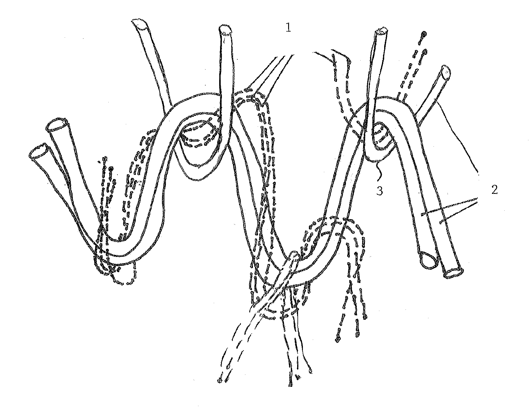
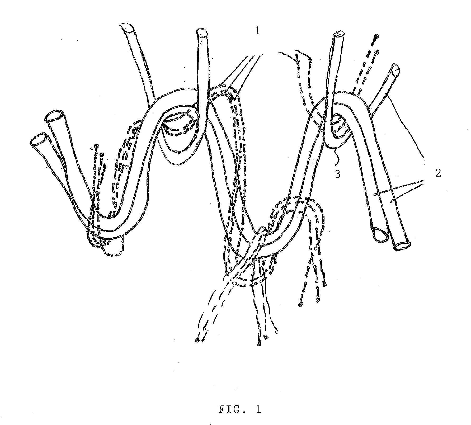

Image

  • Hybrid fabric
  • Hybrid fabric

Examples


Embodiment Construction

[0013]It is the aim of the present invention to provide a hybrid fabric, which may be directly molded onto the patients' body, which shows good breathability to both moisture and heat after having been molded and which provides improved comfort to the patient while providing sufficient immobilization.

[0014]This is achieved according to the present invention with a hybrid fabric showing the technical features of the characterizing portion of the first claim.

[0015]Thereto, the hybrid fabric of this invention is characterized in that the hybrid fabric comprises[0016](1) a first network comprising the structural fibers,[0017](2) a second network comprising the thermo-formable fibers, the thermo-formable fibers comprising non-relaxed fibers made of a thermoplastic material, and[0018](3) a plurality of openings between the fibers of the first and second network, the hybrid fabric further being characterized in that the structural and thermo-formable fibers of respectively the first and se...


PUM

PropertyMeasurementUnit
Temperatureaaaaaaaaaa

Abstract

This invention relates to a hybrid fabric comprising at least one structural fiber having a first melting temperature range and at least one thermo-formable fiber of having a second melting temperature range which is lower than the first melting temperature range to such an extent that the structural fiber does not melt in the second melting temperature range of the thermo-formable fiber. The hybrid fabric comprises (1) a first network comprising the structural fibers, (2) a second network comprising the thermo-formable fibers, the thermo-formable fibers comprising non-relaxed fibers made of a thermoplastic material, and (3) a plurality of openings between the fibers of the first and second network. The structural and thermo-formable fibers of respectively the first and second network interpenetrate one another and are connected to each other over at least part of the first and second network at a plurality of knot positions in the fabric where the structural and thermo-formable fibers are interwoven.

Description

[0001]The present invention relates to a hybrid fabric comprising at least one structural fiber having a first melting temperature range and at least one thermo-formable fiber of having a second melting temperature range which is lower than the first melting temperature range to such an extent that the structural fiber does not melt in the second melting temperature range of the thermo-formable fiber, according to the preamble of the first claim.[0002]In order to be suitable for use in immobilization devices for supporting, stabilizing or immobilizing a limb, joint, muscle, bone or other body part, a material should meet certain requirements. On the one hand the material must be sufficiently rigid, resistant to impact and compression in order to provide good immobilization and minimize the possibility of the body part enclosed by it, to move. In specific applications, such as fractionated medical diagnostic and treatment procedures, for example in radiation oncology, accurate and re...

Claims


Application Information

Patent Timeline
IPC IPC(8): D03D15/00B28B3/00
CPCA61F13/04A61F2013/00238A61L15/12D10B2509/024D04B1/16D10B2401/062A61L15/14Y10T442/30D03D15/587D10B2401/041
Inventor CUYPERS, STEVENBOGDANOV, BOGDAN
Owner ORFIT IND
Learn More