
Image reading apparatus

a technology of image reading and reading body, which is applied in the direction of material analysis using wave/particle radiation, instruments, transportation and packaging, etc., can solve the problems of inability to obtain constant speed conveyance performance, poor conveyance speed irregularity of the conveyance body, image irregularity, etc., to improve the constant speed capability, improve the characteristic of conveyance, and improve the effect of quality

Inactive Publication Date: 2009-03-26
KONICA MINOLTA MEDICAL & GRAPHICS INC
View PDF3 Cites 3 Cited by
  • Summary
  • Abstract
  • Description
  • Claims
  • Application Information

AI Technical Summary

Benefits of technology

[0038]According to the image reading apparatus of the present invention, an optical unit or a photostimulable phosphor plate can be moved at a constant speed to improve a constant speed capability. Further, a preferable image without irregularity can be obtained when scanning the photostimulable phosphor plate by excitation light.
[0039]Further, according to the image reading apparatus and the image forming apparatus including the image reading apparatus of the present invention, a conveyance characteristic can be improved and a high quality image can be obtained by decreasing image irregularity.
[0040]Particularly, according to item (1), since the rub between wires does not occur and a load fluctuation of the pulley can be controlled, the pulley can be rotated with a constant speed. Further, since the rub between the wires does not occur, the durability of the wire itself can be improved.
[0041]According to item (2), since the rub between wires does not occur and a load fluctuation of the pulley can be controlled, the pulley can be rotated with a constant speed. Further, since the rub between the wires does not occur, the durability of the wire itself can be improved.
[0042]According to item (3), the contact between wires does not happen on the pulley so the rub between wires does not occur.
[0043]According to item (4), since the rotational shaft of a rotary encoder and the pulley are integrally formed, the eccentricity caused by the rotation can be suppressed, and the rotary encoder can be rotated with a further constant speed.

Problems solved by technology

However, there is no description about constant speed and there is a possibility that the required constant speed conveyance performance cannot be obtained by only the position detection.
Thus, the conveyance speed irregularity of the conveyance body becomes worse, and image irregularity occurs when scanning the photostimulable prosper plate by photostimulable exciting light.
There was a case that a diagnosis image caused trouble due to this image irregularity.
Further, in case when structuring the image reading apparatus disclosed in the patent document No. 2 so that the conveyance body moves on the horizontal surface, the problem of conveyance irregularity (image irregularity), which did not occur under the vertical conveyance structure of the patent document No. 2, has occurred.
Accordingly, there has been a problem that the conveyance irregularity associated with the rotational movement in a yawing direction and the conveyance irregularity caused by the disturbance of the leaked magnetic flux of the linear motor become large and cause the deterioration of the conveyance performance.
Since the number of parts pertaining to the structure for passing a shaft through the center hole of the magnet and connecting each other is large and cost is high, the shaft type linear motor having a simple structure, in which the repelling magnet is easily and simply stored, has been required.

Method used


Image

  • Image reading apparatus
  • Image reading apparatus
  • Image reading apparatus

Examples


first preferred embodiment

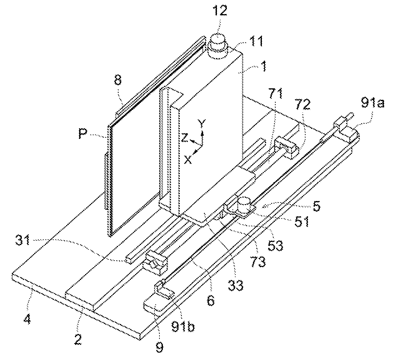
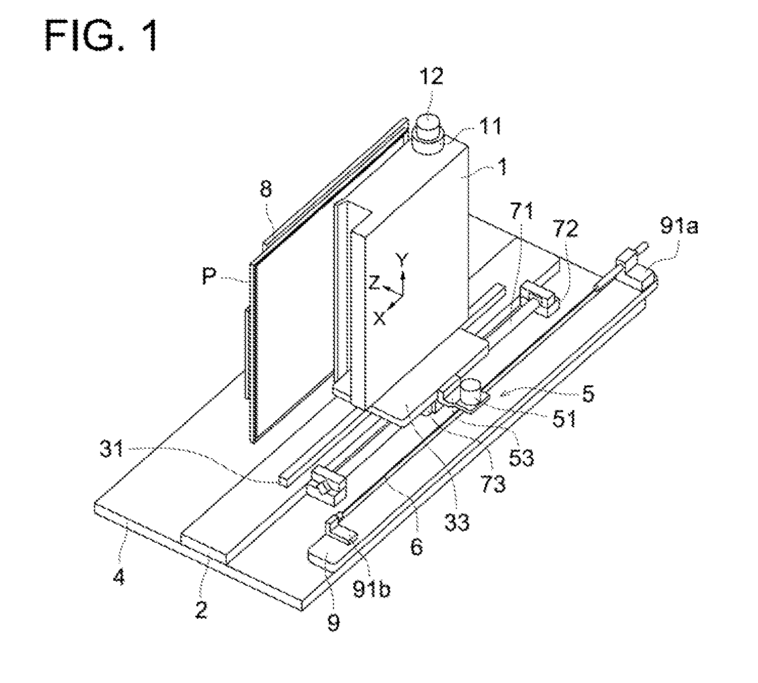
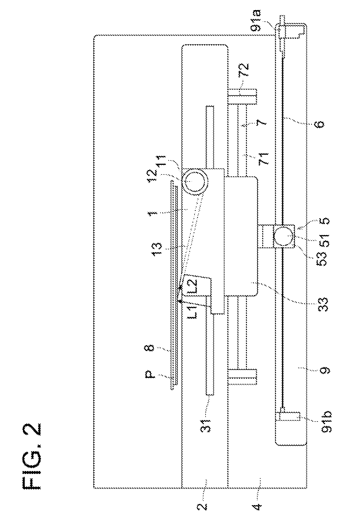
[0123]FIG. 1 shows the perspective view of the transport mechanism in an image reading apparatus according to the first preferred embodiment of the present invention, FIG. 2 is an X-Z plane plan view diagram of the transport mechanism of FIG. 1, FIG. 3 is an X-Y plane plan view diagram of the transport mechanism of FIG. 1, FIG. 4 is an Y-Z plane plan view diagram of the transport mechanism of FIG. 1, and FIG. 5 is a block diagram showing the speed control section of image reading apparatus.

[0124]As is shown in FIGS. 1 to 4, the image reading apparatus is provided with an optical unit 1 that illuminates the stimulable phosphor plate P with laser light (excitation light) from the laser light emitting apparatus (light source) (not shown in the figure) while scanning it and reads the image information by condensing the photo-stimulated luminescence light emitted from the stimulable phosphor plate P and carrying out photoelectric conversion of this light. The image reading apparatus is a...

second embodiment

[0157]FIG. 7 illustrates a perspective view of a conveyance mechanism of an image reading apparatus of a second embodiment of the present invention. FIG. 8 illustrates an X-Z plane view of FIG. 7. FIG. 9 illustrates an X-Y plane view of FIG. 7. FIG. 10 illustrates a Y-Z plane view of FIG. 7.

[0158]In the image reading apparatus of the second embodiment of the present invention, being different from the first embodiment, the optical unit 1 is fixed onto the base table 4 and the photostimulable phosphor plate P is structured so as to move in the horizontal direction.

[0159]In other words, as illustrated in FIGS. 7-10, the optical unit 1 is disposed opposed to the upper surface of the base table 4 and the photostimulable phosphor plate P is disposed between the base table 4 and the optical unit 1. The fixing plate 8 attached on the lower surface of the photostimulable phosphor plate P is fixed on the traveling board 33, which is able to move against the base table 4. As a result, the opt...

third embodiment

[0208]FIG. 1 illustrates a perspective view of a conveyance mechanism of an image reading apparatus of the third embodiment. FIG. 2 illustrates an X-Z plane view of FIG. 1. FIG. 3 illustrates an X-Y plane view of FIG. 1. FIG. 4 illustrates a Y-Z plane view of FIG. 1. FIG. 11 illustrates a block diagram showing a feedback control section of the image reading apparatus.

[0209]As illustrated in FIG. 1-FIG. 11, an image reading apparatus including

[0210]an optical unit (a reading section) 1 for reading the image information by irradiating with laser beam from a laser beam irradiating apparatus (not shown) to a photostimulable phosphor plate (recording medium) P while scanning and converging photostimulable luminescence light emitted from the photostimulable phosphor plate P for photoelectric conversion, and

[0211]a linear motor (a conveyance device) 7 for moving the optical unit (a conveyance body) 1, with a guide rail 31 for guiding the optical unit 1 in a horizontal direction being suppo...


PUM


Abstract

An image reading apparatus includes an optical unit for reading the image information by scanning and irradiating the photostimulable phosphor plate with the excitation light from a light source and converging photo-stimulated luminescence light emitted from the photostimulable phosphor plate to conduct photoelectric conversion, a base table, a linear motor for moving the optical unit with respect to the base table, a wire fixed on the base table at both ends of the wire, a pulley rotatably fixed on the optical unit for being rotated by relative movement between the pulley and the wire caused by the movement of the optical unit, a rotary encoder for detecting a rotational speed of the pulley; and a control section for controlling the linear motor based on a detection result of the rotary encoder, wherein the wire is wound not less than one turn around the pulley and inclined at a predetermined angle against a line crossing a rotational axis of the pulley at right angle.

Description

FIELD OF THE INVENTION[0001]This invention relates to an image forming apparatus, particularly relates to an image reading apparatus including a shaft type linear motor having a superiority in scan-conveyance capability of a photostimulable phosphor plate, which is suitable for the usage in a medical field and a printing field.BACKGROUND[0002]Radiographic images such as X-ray images are used extensively for diagnosis of illness. Conventionally, in order to obtain such radiographic images, the so-called radiographs were used in which the X-rays passing through the subject impinged on a phosphor layer (fluorescent screen) thereby generated visible light, and this visible light impinged on a film using silver salts as in normal photography and this film was developed. However, in recent years, methods that use no films coated with silver salts but directly take out images from the phosphor layer have been devised.[0003]In an example of such a method, the radiation that has passed throu...

Claims


Application Information

Patent Timeline
IPC IPC(8): G01N23/02
CPCG03B42/02H04N1/1017H04N2201/0081H04N2201/0079H04N1/1026
Inventor UMEMURA, MASAHIROSAKINO, KAZUHIRONARITA, TAKAYUKI
Owner KONICA MINOLTA MEDICAL & GRAPHICS INC
Learn More