Solar powered battery charger using switch capacitor voltage converters

a technology of switch capacitor and voltage converter, which is applied in the direction of photovoltaic energy generation, secondary cell charging/discharging, electric vehicles, etc., can solve the problems of limiting current output and limiting conversion ratio, and achieve the effect of reducing costs, eliminating emi concerns and battery drainag

Inactive Publication Date: 2009-03-26
MSR INNOVATIONS
View PDF7 Cites 62 Cited by
  • Summary
  • Abstract
  • Description
  • Claims
  • Application Information

AI Technical Summary

Benefits of technology

[0006]There is thus a need to provide a simple battery charger powered by solar that can reduce costs, eliminate EMI concerns and battery drainage, and effectively utilize solar module area. The battery charger of the invention provides a significant advantage by eliminating the inductor through the use of switched capacitor voltage converters. These are also called inductor-less DC / DC converter / regulators or charge pumps, which are capable of full integration. The circuit using switched capacitor voltage converters is simple and low cost when used with an integrated circuit. Integrated circuits (ICs) are readily available through many manufacturers, examples being Analog Device, Linear Technology, Texas Instruments, National Semiconductor, and Dallas Semiconductor. This invention also solves the complexity of providing a common ground, which limits the battery equal charge configurations. Moreover, since they require no external inductor, switched capacitor converters solve EMI issues related to inductor-based converters, as introduced in U.S. Pat. No. 7,030,597. Furthermore, the “boost” topology of this design results in a solar module output as low as 2V, which results in less cell cuts, fully utilized solar module area, and simple cell interconnection. Another advantage of this invention is that the battery overcharge problem can be avoided. The system does not drain power from the battery because the system power supply is controlled by the photovoltaic voltage. The system is automatically powered up when the photovoltaic power is available and is turned off when photovoltaic power is not available.

Problems solved by technology

One drawback of using switched capacitor voltage converters is the limit of current output, typically less than 1 A. Unlike regular switching-mode converters, certain combinations limit the conversion ratio.

Method used


Image

  • Solar powered battery charger using switch capacitor voltage converters
  • Solar powered battery charger using switch capacitor voltage converters
  • Solar powered battery charger using switch capacitor voltage converters

Examples


Embodiment Construction

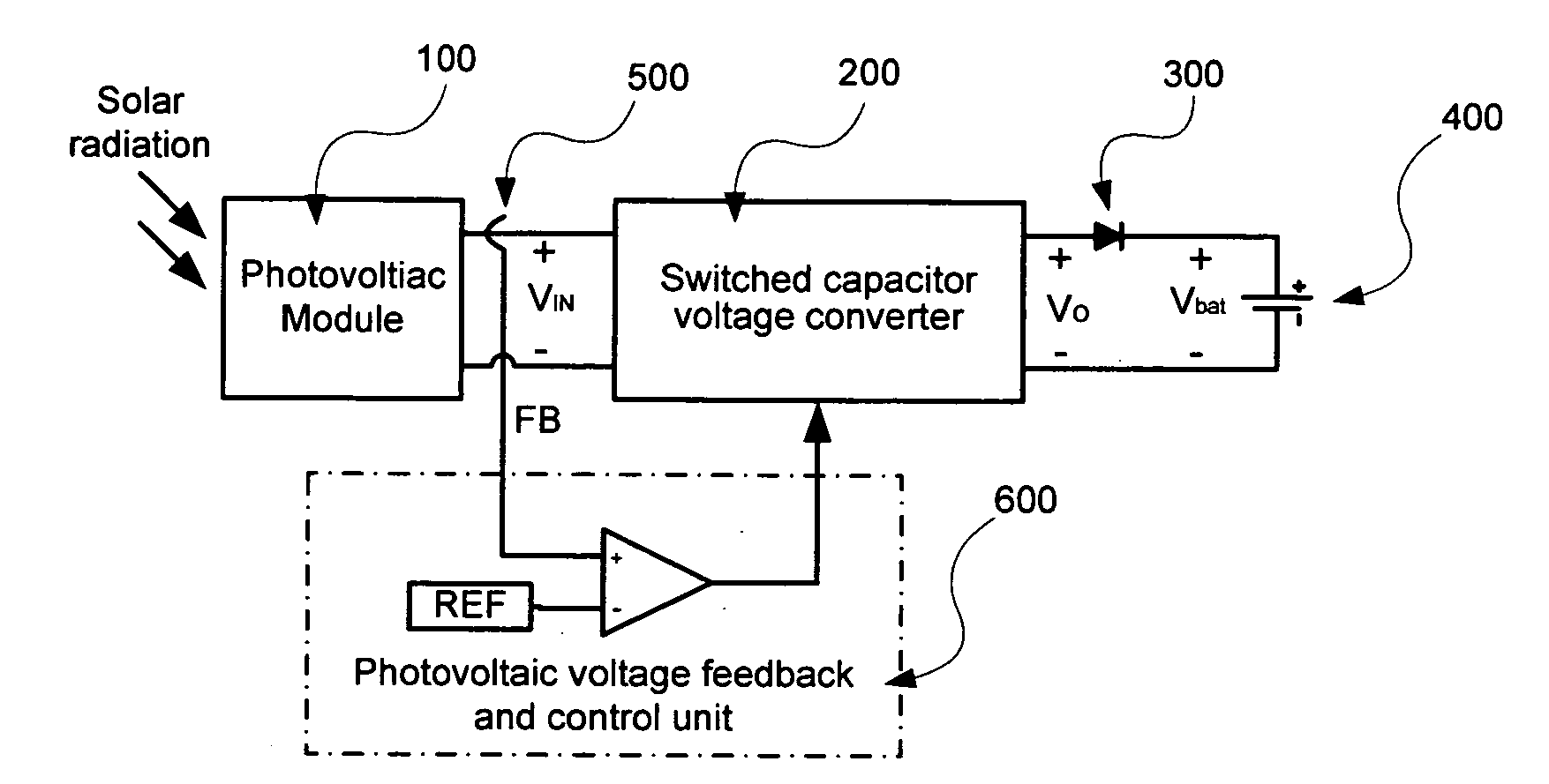
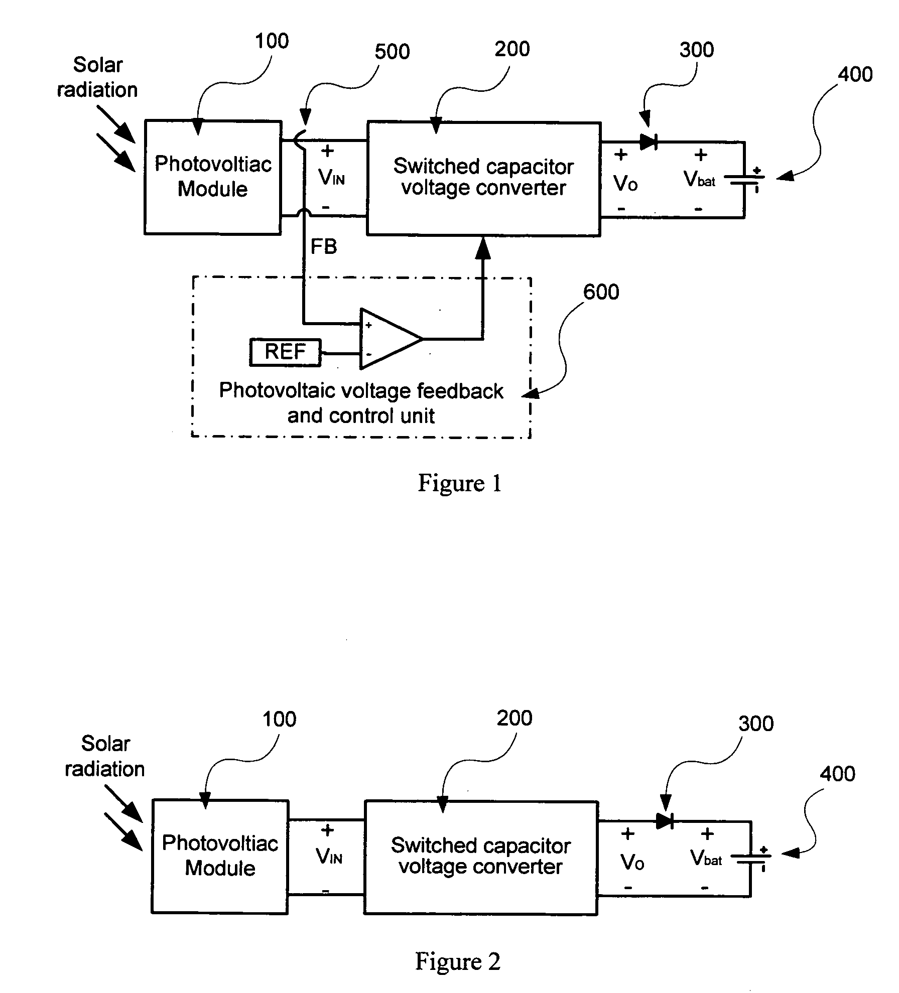
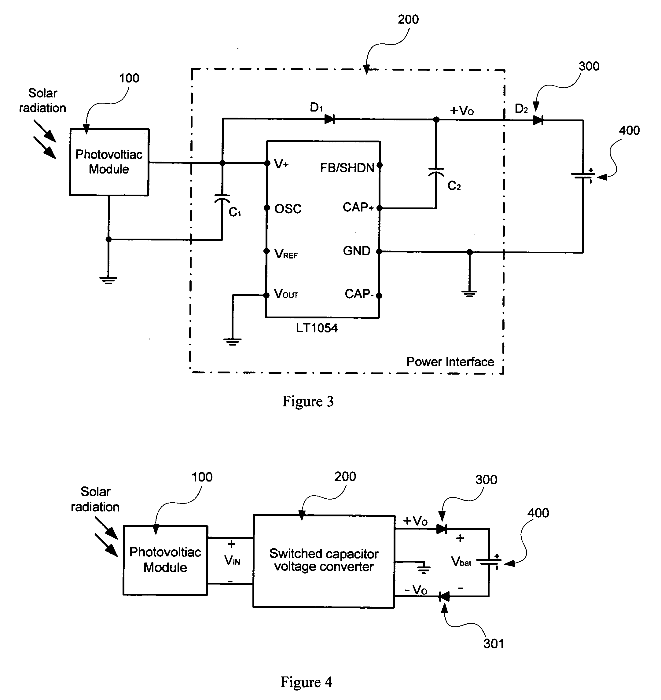
[0020]FIG. 1 shows an embodiment of the invention. The photovoltaic module (100) produces electric power when it is exposed to sunlight. To charge the battery (400), the switched capacitor voltage converter (200) serves as the power interface, which adopts the solar power and converts the voltage to a certain level, Vo. The power interface (200) can be comprised of a voltage doubler, and / or a voltage inverter, and / or a voltage tripler, or a combination of these topologies.

[0021]When solar power is available, the output voltage, Vo, should be higher than the battery voltage, Vbat. The capacity of photovoltaic power generation depends heavily on the presence of sunlight. At night, a current may flow back to the photovoltaic cells from devices that can supply electric power. This reverse current must be avoided because it can result in leakage loss, extensive damage, or even fire. The blocking device (300) should be used to prevent this reverse current flow.

[0022]In terms of maximum po...


PUM


Abstract

The invention provides a charging device that uses switched capacitor voltage converters to charge a battery using solar power. The charger uses boosting topology to efficiently use solar module photovoltaic power. The boosting topology enables a lower voltage to be used resulting in reduced cutting and soldering of photovoltaic cells. The battery charger has overcharge protection and uses inductor-less circuitry.

Description

[0001]This application claims priority from provisional patent application No. 60 / 974,242 filed on Sep. 21, 2007.BACKGROUND INFORMATION [0002]There are numerous methods available for battery charging. Battery lifetime is directly related to how “deep” a battery is cycled (charge / discharge) each time. To extend the life of a battery, it is important to maintain a light battery cycle (i.e. keep deep cycling to a minimum). Certain batteries have low duty-cycle applications where the battery power is required infrequently. Self-discharge of the battery can result in losing some, or most, of the overall capacity. Applying trickle-charging can prolong the battery lifetime and keep the full battery capacity ready for immediate application.[0003]Trickle charging, also called float charging or slow charging, is a battery charging method to maintain a full capacity battery during self-discharge. A solar powered battery charger, producing clean and free energy when exposed to sunlight, can pro...

Claims


Application Information

Patent Timeline
Patent Type & Authority Applications(United States)
IPC IPC(8): H02J7/35
CPCH02J7/35Y02E10/566H02M3/1584H02M3/07Y02E10/56
Inventor XIAO, WEIDONGRODDICK, TIMOTHY JAMESSCULTETY, JASON LEONARD
Owner MSR INNOVATIONS
Why Eureka
Try Eureka