

Bonded structure and method of making the same, head gimbal assembly, head stack assembly and disk drive unit using the same
a technology of bonded structure and bonded structure, which is applied in the direction of maintaining the head carrier alignment, recording information storage, instruments, etc., can solve the problems of affecting the electric function of the head gimbal assembly b>150/b>, the surrounding components of both flexure and flexible printed circuits are damaged, and the pressure might damage the surrounding components of both flexure and flexible printed circuits, etc., to achieve high manufacturing yield, avoid short circuit, and high quality
- Summary
- Abstract
- Description
- Claims
- Application Information
AI Technical Summary
Benefits of technology
Problems solved by technology
Method used
Image

Examples
first embodiment
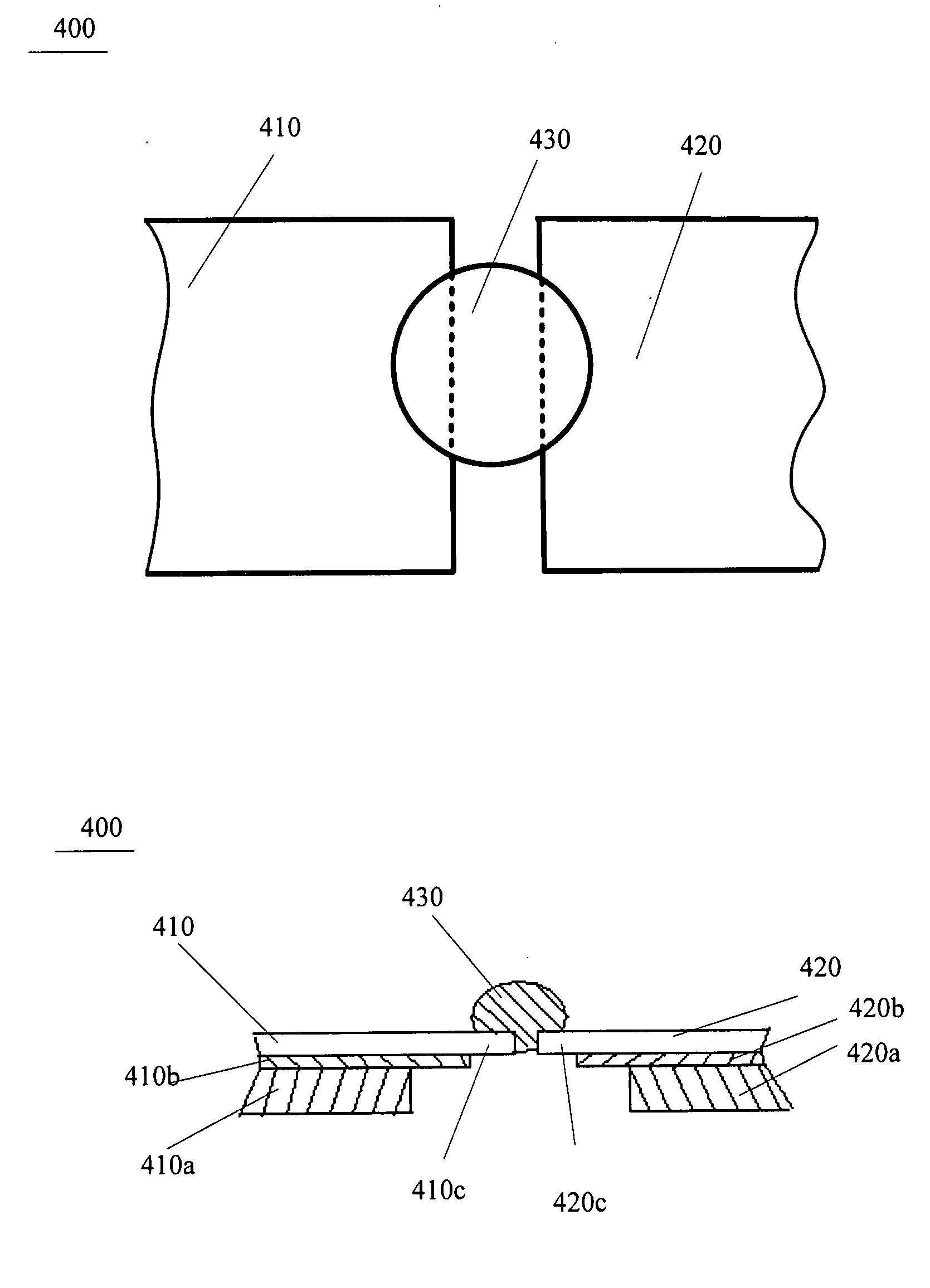
[0059]FIGS. 5a-5b illustrate the principle of a bonded structure 400 for two electrical components according to the present invention. The bonded structure 400 comprises a first electrical pad 410 disposed on one electrical component, a second electrical pad 420 disposed on the other electrical component and metal ball 430 for bonding or welding the first electrical pad 410 and the second electrical pad 420. It is appreciated that the metal ball 430 could be solder ball or gold ball. The two electrical components respectively have a first substrate layer 410a / 420a and a second substrate layer 410b / 420b laminated on the first substrate layer 410a / 120a. The second substrate layer 410b / 420b might be formed of polymer material. The first electrical pad 410 and the second electrical pad 410 each have an attaching surface attached to the second substrate layers 410b / 420b of the respective electrical components, a bonding surface opposite the attaching surface. Both the bonding surfaces of...
second embodiment
[0060]FIG. 6 illustrates the principle of a bonded structure 500 according to the present invention. The bonded structure 500 comprises a first electrical pad 510, a second electrical pad 520 and a metal ball 530. The bonded structure 500 in the subject embodiment is similar to the bonded structure 400 mentioned above except that the first electrical pad 510 is L-shaped and the second electrical pad 520 is also L-shaped. The first electrical pad 510 and the second electrical pad 520 are complementarily aligned with each other on the same level.
third embodiment
[0061]FIG. 7 illustrates the principle of a bonded structure 600 according to the present invention. The bonded structure 600 comprises a first electrical pad 610, a second electrical pad 620 and a metal ball 630. The bonded structure 600 in the subject embodiment is similar to the bonded structure 400 mentioned above except that the first electrical pad 610 is trapezoidal in shape and the second electrical pad 620 is also trapezoidal in shape. The first electrical pad 610 and the second electrical pad 620 are complementarily aligned with each other on the same level.
[0062]FIGS. 8a-8b illustrate the principle of a bonded structure 700 of two components according to a fourth embodiment of the present invention. The bonded structure 700 comprises a first electrical pad 710 disposed on one electrical component, a second electrical pad 720 disposed on the other electrical component and metal ball 730 for bonding or welding the first electrical pad 710 and the second electrical pad 720.T...
PUM
 Abstract
Description
Claims
Application Information