Vcm driver and pwm amplifier

a vcm driver and amplifier technology, applied in the direction of instruments, recording information storage, head support, etc., can solve the problems of reducing the track interval, reducing the accuracy of the pwm method, and reducing the accuracy of the vcm method, so as to improve the output distortion, improve the accuracy of tracking operation, and improve the effect of accuracy

Inactive Publication Date: 2009-03-26
RENESAS ELECTRONICS CORP
View PDF9 Cites 14 Cited by
  • Summary
  • Abstract
  • Description
  • Claims
  • Application Information

AI Technical Summary

Benefits of technology

[0005]In the VCM driver of Patent Document 2 or 3, PWM drive is entirely adopted by devising methods of (1) using a current amplifier with a phase compensator realized by a digital filter, (2) reducing a quantization error caused by PWM modulation of an output by ΔS modulation, (3) reducing a switching error by measuring the delay time and transition time of a switching waveform of an output stage, and (4) reducing a PWM modulation error of an output stage by measuring the power supply voltage of the output stage with the ADC. In this case, a noise generated by the DAC and a noise caused by the phase compensator of the VCM driver are reduced. However, a high recording density corresponding to a vertical recording method or the like as described above causes the following problems.
[0007]An object of the present invention is to provide a VCM driver realizing low power consumption and high accuracy. Another object of the present invention is to provide a PWM amplifier reducing a dead time distortion and suitable for a VCM driver and the like. The above and further objects and novel features of the present invention will be apparent from the following description of this specification and the accompanying drawings.
[0009]A second-order error suppression characteristic can be obtained at a drive end of a VCM by a negative feedback effect of the minor feedback loop and a negative feedback effect of the major feedback loop, so that both of an error and a zero-crossing distortion at an output stage caused by a power supply variation are reduced and an accurate tracking operation becomes possible. A zero-crossing (dead time) compensation circuit makes accurate tracking possible and is able to improve an output distortion as a PWM amplifier.

Problems solved by technology

When the recording density is increased like this, the track interval is reduced and the accurate tracking thus becomes difficult in the PWM method.
At that time, also in a liner method shown in Patent Document 1, a quantization noise, a 1 / f noise, or a white noise which arises at digital-to-analog conversion becomes a large obstacle at a track following time when the magnetic head is allowed to follow a required track for read and write.
However, a high recording density corresponding to a vertical recording method or the like as described above causes the following problems.
In the PWM amplifier of Patent Document 2, a control dead band arises near a zero-crossing point of a coil current by a dead time of the output switching circuit, thus causing a large noise (occurrence of a zero-crossing distortion).
As a result of this, accurate tracking becomes impossible and the output distortion becomes large for the PWM amplifier.
Furthermore, an ADC is necessary to correct an output error (PWM error) to a power supply variation, thereby increasing the cost.
The update rate of an input signal is not synchronized with the update rate of the output-side ΔS modulator and there is little frequency difference between them, so that the generation of a beat noise is feared.
A control band is restricted by a delay caused by an LPF or decimation filter subsequent to a ΔS ADC, so that it is difficult to achieve a control band desired by a hard disk drive (HDD) using a vertical recording method.

Method used


Image

  • Vcm driver and pwm amplifier
  • Vcm driver and pwm amplifier
  • Vcm driver and pwm amplifier

Examples


Embodiment Construction

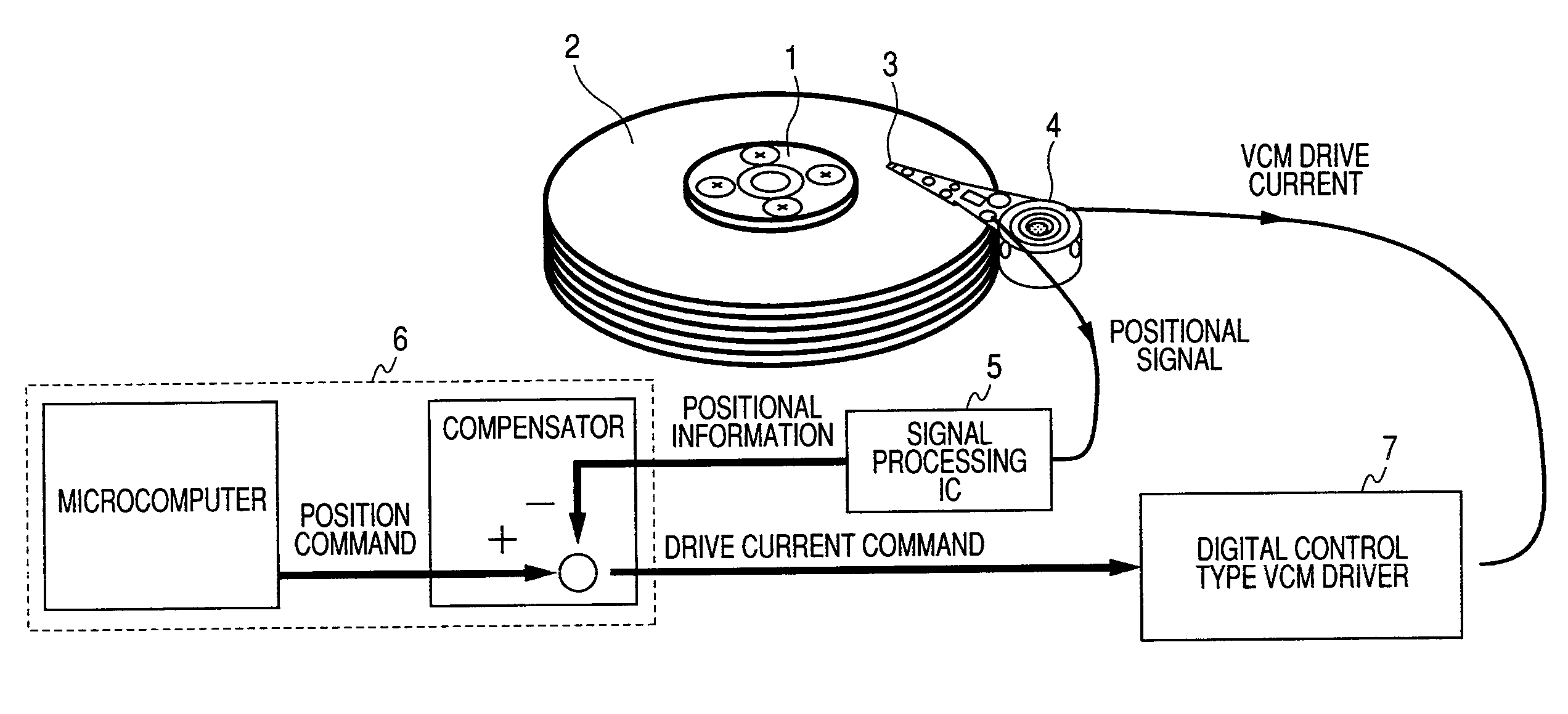
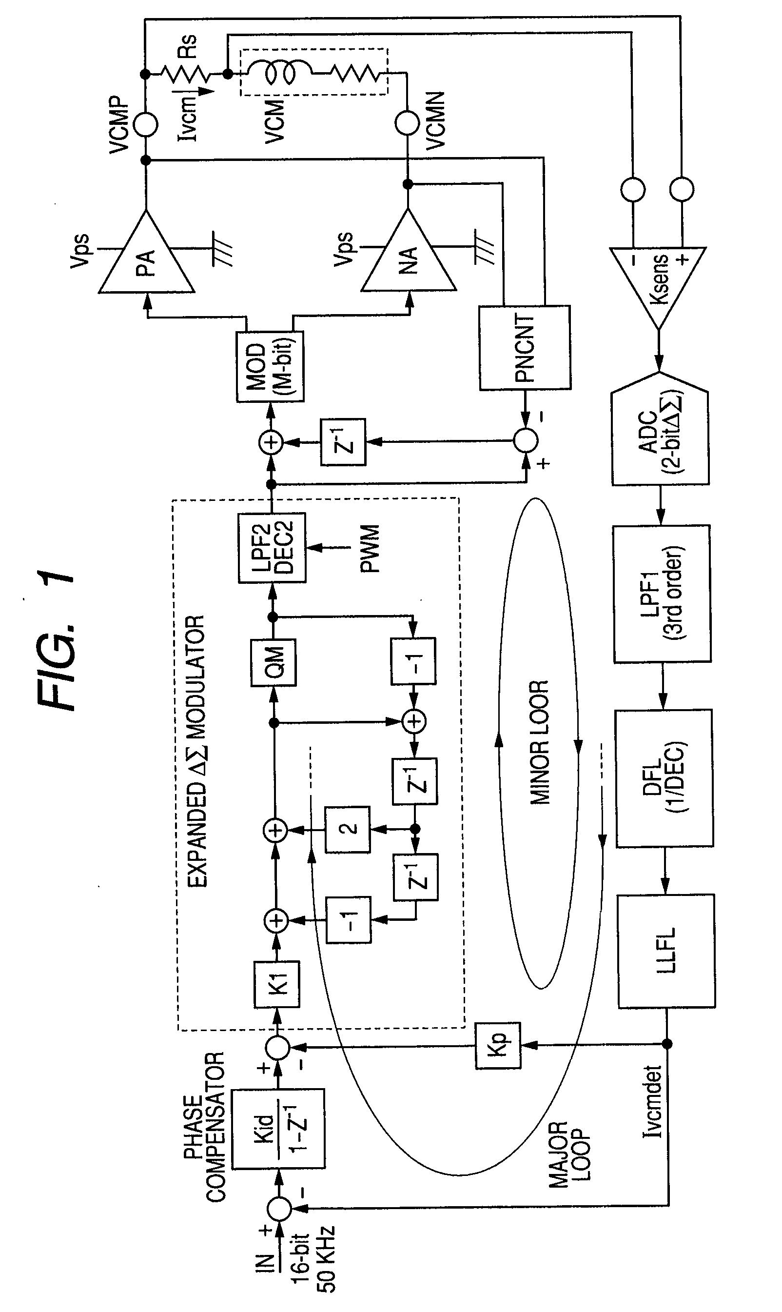
[0025]FIG. 1 is a block diagram of an embodiment of a VCM driver according to the present invention. The VCM driver of FIG. 1 has a forward path for supplying a drive current to a voice coil VCM and a feedback path for sensing the drive current of the voice coil VCM. The forward path includes a phase compensator, an expanded ΔΣ modulator, MOD, PA, and NA. The feedback path includes Ksens, ADC, LPF1, DFL, and LLFL. The MOD is a PWM modulator. The PA and NA are output circuits. The Ksens is a sense amplifier. The LPF1 is a low-pass filter. The DFL is a decimation filter. The LLFL is a lag-lead filter.

[0026]The forward path is as follows. An input signal IN is a drive current command, for instance, a 16-bit digital signal. The input signal IN is produced by a controller including a microcomputer described later, and is input to the forward path through a serial input / output port not shown in the figure. The update rate (frequency) of the input signal IN is the order of 50 kHz in a pres...


PUM

PropertyMeasurementUnit
frequencyaaaaaaaaaa
frequencyaaaaaaaaaa
currentaaaaaaaaaa

Abstract

The present invention provides a VCM driver realizing low power consumption and high accuracy and a PWM amplifier compensating a dead time distortion. A phase compensator, a ΔS modulator receiving an output signal of the phase compensator and converting the output signal to a control code of predetermined bits, a PWM modulator receiving the control code to produce a PWM signal, and an output circuit receiving the PWM signal to drive a voice coil constitute a forward path. A sense amplifier sensing a current of the voice coil, an ADC receiving an output signal of the sense amplifier, a low-pass filter receiving an output signal of the ADC, and a decimation filter receiving an output signal of the low-pass filter constitute a feedback path. An output signal of the decimation filter is fed back to the input side of the phase compensator to form a major feedback loop having a first-order characteristic loop gain. An output signal of the decimation filter is fed back to the output side of the phase compensator to form a minor feedback loop having a loop gain which is flat until a target band frequency when viewed from the output side of the phase compensator.

Description

CROSS-REFERENCE TO RELATED APPLICATION[0001]The present application claims priority from Japanese patent application No. 2007-243662 filed on Sep. 20, 2007, the content of which is hereby incorporated by reference into this application.BACKGROUND OF THE INVENTION[0002]The present invention relates to a voice coil motor (VCM) driver and a pulse width modulation (PWM) amplifier, and in particular to a technology effectively applied to a VCM driver and a PWM amplifier used for, for example, a hard disk memory device.[0003]In a hard disk drive device, seek-time needed for movement between tracks tends to be shortened from the viewpoint of high speed access. As a result of this, the drive current of a voice coil motor (VCM) has increased and heat generation at a seek operation has become a problem. In order to solve this heat generation problem, the power consumption is reduced by pulse width modulation (PWM) drive only in the seek period of time when accurate positioning control is not ...

Claims


Application Information

Patent Timeline
Patent Type & Authority Applications(United States)
IPC IPC(8): G11B5/54H02P25/06
CPCG11B5/5526G11B5/5547
Inventor KOKAMI, YASUHIKOKUROIWA, HIROSHI
Owner RENESAS ELECTRONICS CORP
Why Eureka
Try Eureka