Method of forming an article

Inactive Publication Date: 2009-03-26
MATERIALS SOLUTIONS
View PDF1 Cites 19 Cited by
  • Summary
  • Abstract
  • Description
  • Claims
  • Application Information

AI Technical Summary

Benefits of technology

[0038]A method of achieving this is to form an attachment part for the first part at the same time as the first part and by the same means as the first part

Problems solved by technology

By their very nature these supports are not part of the desired geometry and therefore need to be designed, built and removed.
This is both time consuming and requires skill thereby adding delay and cost.
A further problem is that the geometry of the part may be such that it is difficult or impossible to locate support structures that can be removed—thereby limiting the geometries that can be made by the DLD process.
Whil

Method used


Image

  • Method of forming an article
  • Method of forming an article
  • Method of forming an article

Examples


Embodiment Construction

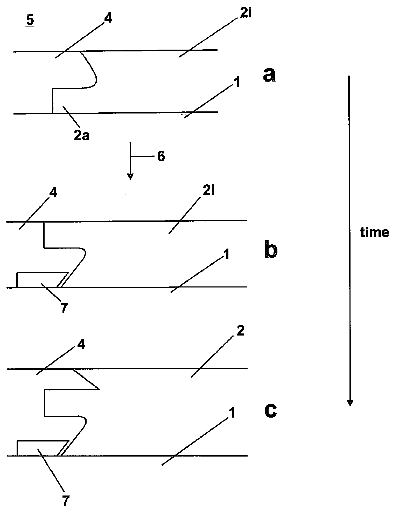
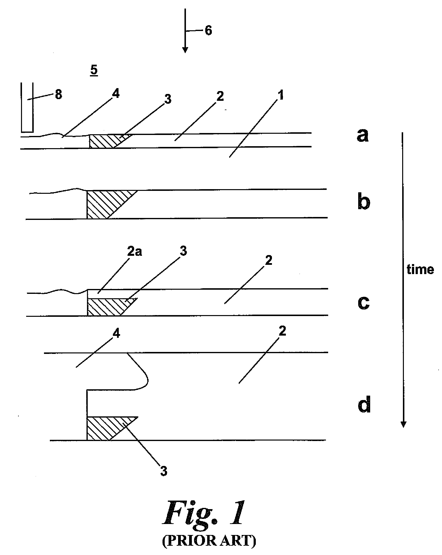
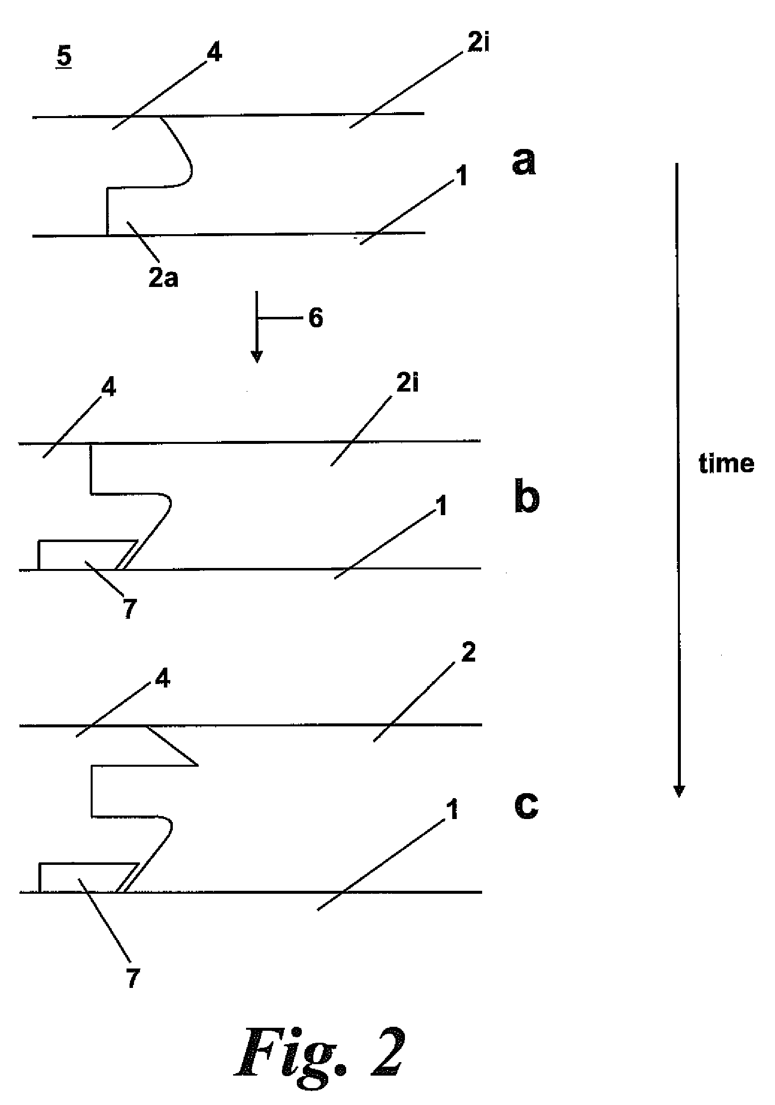
[0044]FIGS. 1a and b show intermediate stages of the powder bed SLS / SLM process. The start point is a base plate 1 and powder 4. A thin layer of powder is placed by various means familiar to those familiar with these machines across the base plate—e.g. by pushing powder from a powder source bin with a re-coater blade 8. A point source of energy 6 such as a laser beam is directed at the powder causing it to fuse to form a solid 2 being part of a desired 3 dimensional solid object. The base plate is indexed downwards and a fresh layer of powder created across the base plate and the solid 2 in build. The ambient 5 is an inert gas such as argon or is de-oxygenated air. Typically the base plate 2 is warmed to above ambient to enable easy thermal control. At 3 a support structure is being built. This is not a desired part of the solid object but is required by a subsequent part of the building process. Such supports can be custom designed or generated automatically by “Magics” software fr...


PUM

PropertyMeasurementUnit
Temperatureaaaaaaaaaa
Timeaaaaaaaaaa
Dimensionaaaaaaaaaa

Abstract

A method of making an article includes determining the greatest dimension of an article along a selected axis, and manufacturing a first part of the article between an end and a face lying in the laterally extending plane containing the dimension. The method further includes placing the article on the support of direct layer deposition (DLD) apparatus with the face upwards, and forming the remaining part of the article using the DLD apparatus.

Description

BACKGROUND AND SUMMARY[0001]This invention relates to a method of forming an article.[0002]The laser sintering / melting of powdered materials to form solid parts is now well known, though the forming of nominally 100% dense metal parts by a practical process is relatively new.[0003]In particular there are commercial powder bed ‘Selective Laser Sintering’ / ‘Selective Laser Melting’ (SLS / SLM) machines such as the M270 produced by Electron Optical Systems (EOS) M270 and the Realizer II marketed by MCP. These take metal powders under an inert atmosphere and direct a CO2 or fibre laser onto a layer of powder.[0004]There are other similar powder bed machines and somewhat related processes such as ‘Direct Laser Fabrication’ (blown powder). Generically a point source of energy such as a laser or electron beam is selectively applied to a layer of powder and a 3D part built up layer wise from a ‘slicing’ of a design file. The heat from the point source melts or sinters the particulates to form ...

Claims


Application Information

Patent Timeline
IPC IPC(8): B22F3/105
CPCB22F3/1055B22F2998/00C22C1/0433C22C1/0458B22F7/06Y02P10/25B22F10/28B22F10/66B22F10/32
Inventor ILLSTON, TREVOR JOHN
Owner MATERIALS SOLUTIONS
Why Eureka
Try Eureka