Method and apparatus for particle filtration and enhancing tool performance in film deposition

Active Publication Date: 2009-04-02
MSP
View PDF50 Cites 17 Cited by
  • Summary
  • Abstract
  • Description
  • Claims
  • Application Information

AI Technical Summary

Benefits of technology

[0012]The same approach can also be used to replace other system components that are in contact with the process gas stream and need to be removed for maintenance

Problems solved by technology

Particles carried by the gas/vapor mixture into the deposition chamber can deposit on the wafer surface causing harmful effects, including the loss of product yield.
Product yield loss due to particulate contamination is a major cause of decreased product output in a semiconductor device fab.
Left uncontrolled, particulate contamination can severely impact the productivity and profitability of the device fab.
One consequence of using a filter in a film deposition apparatus, also referred to as a tool, is that the filter can get clogged during use due to particle accumulation in the filter.
A clogged filter will cause an increase in filter pressure drop.
A clogged filter can also cause particle shedding, resulting in particles collected on the filter being re-entrained by the gas/vapor flow, and resuspended in the mixture stream.
Removing a filter or a vaporizer from a film deposition tool, will require shutting down the tool resulting in the loss of productive use of the tool time for film

Method used


Image

  • Method and apparatus for particle filtration and enhancing tool performance in film deposition
  • Method and apparatus for particle filtration and enhancing tool performance in film deposition
  • Method and apparatus for particle filtration and enhancing tool performance in film deposition

Examples


first embodiment

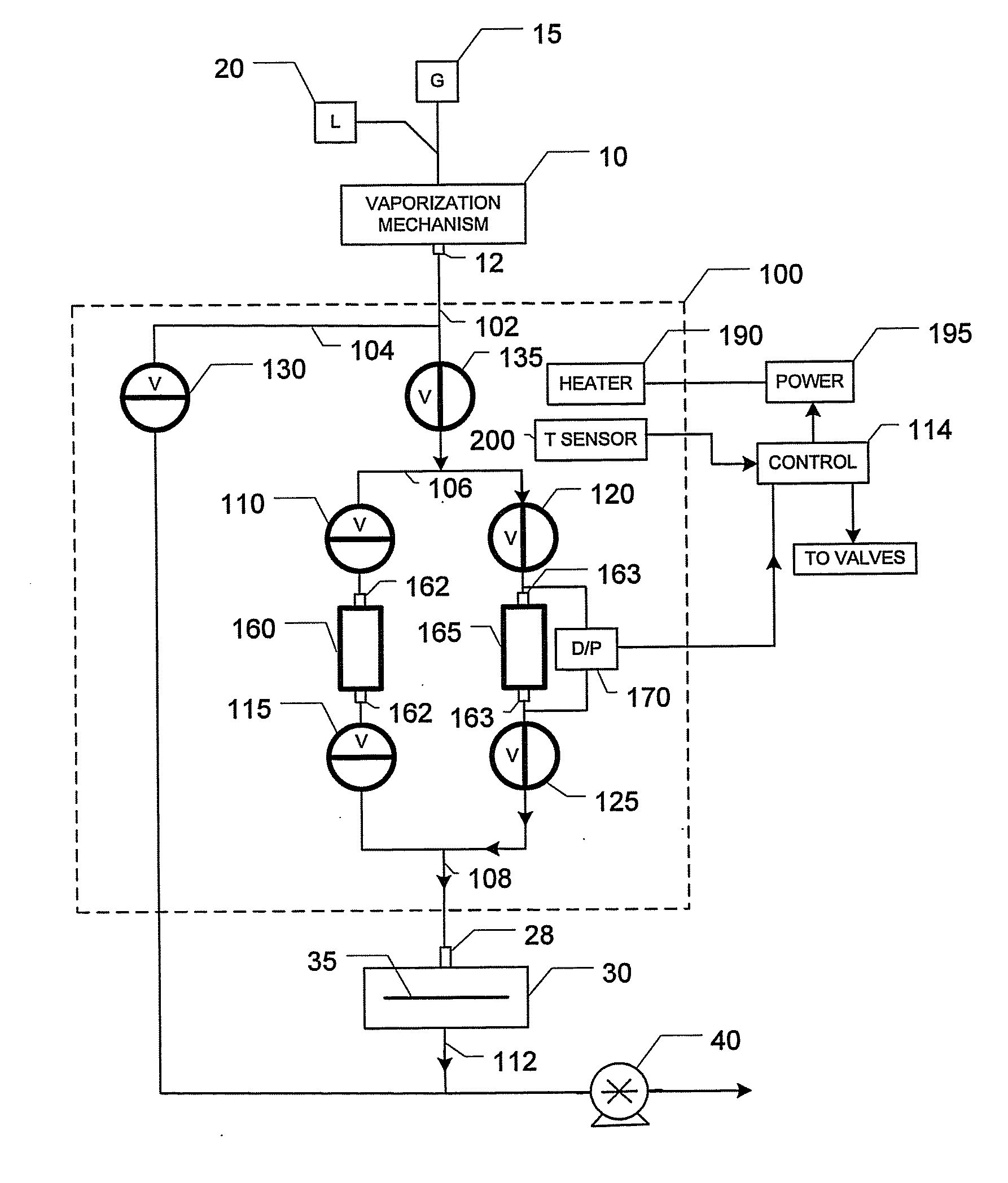
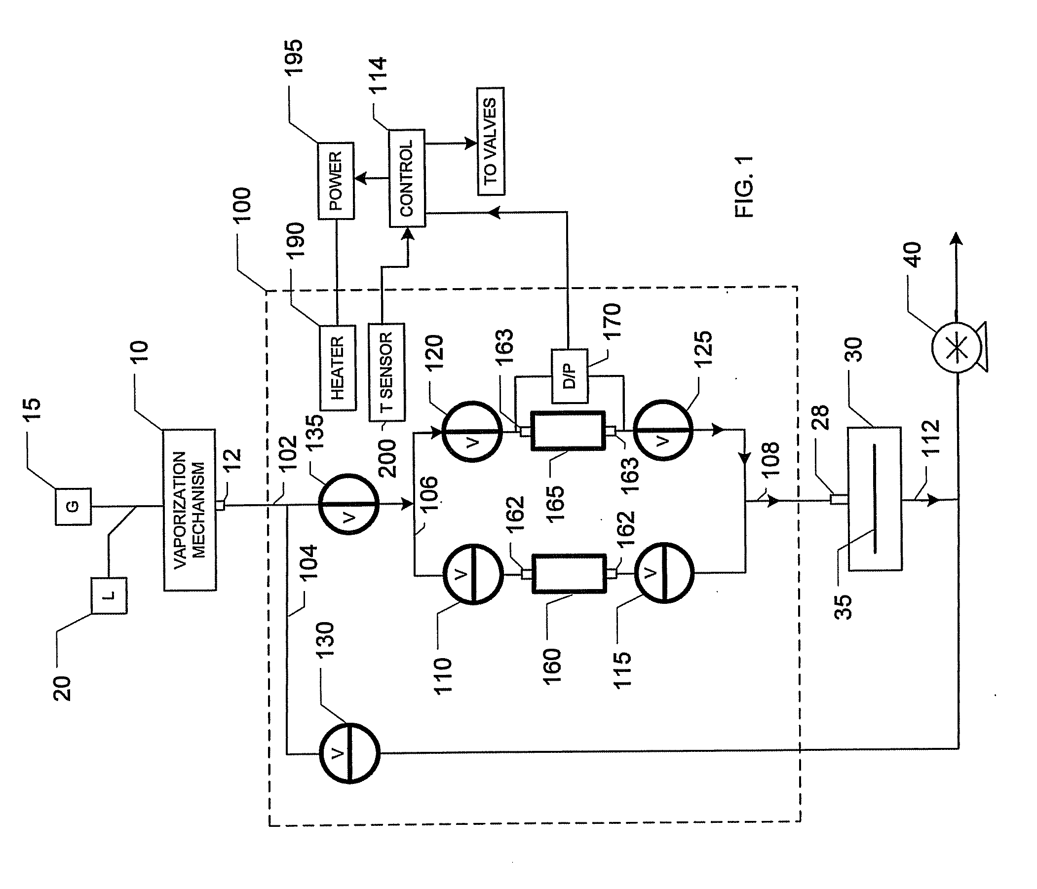
[0017]FIG. 1 shows the present disclosure. A film deposition system or tool 8 includes a vaporizer 10, a vacuum deposition chamber 30 containing a wafer 35, as shown a semiconductor wafer, on which a film is to be deposited, and a vacuum pump 40 for creating a suitable vacuum in chamber 30 for thin film deposition on the wafer 35 by gas / vapor phase processes. The system input flow lines connected to the chamber 30 are also under vacuum during operation. Placed between vaporizer 10 and the deposition chamber 30 is a valve and filter apparatus shown generally at 100. For brevity, apparatus 100 is referred to as a VF apparatus or VFA for short. When used in the manner described below the VFA will allow a clogged filter to be removed without breaking the system vacuum. The film deposition tool can thus continue to operate without being shut down for filter maintenance or replacement.

[0018]The vaporizer 10 is connected to a source of gas 15, and a source of liquid 20. The gas and liquid ...

second embodiment

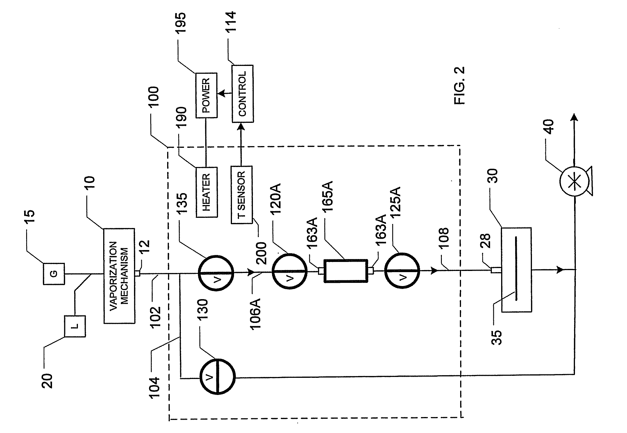
[0030]FIG. 2 shows the present invention. It is simpler than the embodiment shown in FIG. 1. The numbers of like components described in FIG. 1 are the same in FIG. 2. In FIG. 2, there is only one single filter, 165A, and a single set of isolation valves. The branched flow conduit 106 is replaced with a flow conduit 106A from the valve 135 to the valve 120A, which connects to filter 165A and to valve 125A. The isolation valves 120A and 125A are used to isolate filter 165A when the filter gets clogged, allowing it to be removed and replaced by a new filter, using disconnectable connectors 163A at the inlet and outlet ends, without breaking the deposition system vacuum as explained earlier, by having the connectors 163A between the valve 120A and the inlet of the filter 165A and between the outlet of filter 165A and the valve 125A. Without a second filter and a second set of isolation valves (filter 160 and valves 110 and 115 in FIG. 1), the system in FIG. 2 will not permit production...


PUM

PropertyMeasurementUnit
Temperatureaaaaaaaaaa
Flow rateaaaaaaaaaa
Vacuumaaaaaaaaaa

Abstract

This disclosure pertains to a method and apparatus to permit changing a filter on the input line to a vacuum deposition chamber without breaking or reducing the vacuum for the deposition chamber and other components in the deposition system. Isolation valves are provided at the inlet and outlet of the filter so the filter can be isolated from the source of vacuum and the deposition chamber for removal and replacement of the filter.

Description

CROSS REFERENCE TO RELATED APPLICATIONS[0001]This disclosure claims priority based on U.S. provisional Application Ser. No. 60 / 997,197, filed Oct. 2, 2007 and also claims priority based on U.S. provisional Application Ser. No. 60 / 999,280, filed Oct. 17, 2007, the disclosures of both applications Ser. No. 60 / 997,197 and 60 / 999,280 are incorporated by reference in their entireties.BACKGROUND OF THE DISCLOSURE[0002]The present disclosure relates to a method and apparatus to permit changing a filter on the input line to a vacuum deposition chamber without breaking or reducing the vacuum for the deposition chamber or for the rest of the deposition system.[0003]In thin film deposition for semiconductor applications, it is often necessary to vaporize a precursor chemical in liquid or solid form to generate a vapor. Film deposition can then take place by a vapor phase process such as chemical vapor deposition (CVD), atomic layer deposition (ALD), and other known processes. A carrier gas is ...

Claims


Application Information

Patent Timeline
IPC IPC(8): C23C16/00B23P6/00
CPCY10T29/4973C23C16/4402H01L21/205
Inventor LIU, BENJAMIN Y.H.MA, YAMINDINH, THUC M.
Owner MSP
Why Eureka
Try Eureka