
Reduced-pressure heat treatment jig and reduced-pressure heat treatment method

a heat treatment jig and heat treatment technology, applied in heat treatment equipment, lighting and heating equipment, furniture, etc., can solve problems such as defective products and adherence between heat treatment jigs, and achieve the effect of reliably preventing adherence between workpieces and jigs

Inactive Publication Date: 2009-04-02
AISIN AW CO LTD
View PDF3 Cites 15 Cited by
  • Summary
  • Abstract
  • Description
  • Claims
  • Application Information

AI Technical Summary

Benefits of technology

[0015]The jig of the present aspect of the present invention is formed with a film formed of the material described above, and the film persists without evaporating or the like during the heat treatment. Therefore, the surface of the jig where the film is formed continues to be covered by the film without an appearance of the newly-formed surface of the iron material. Thus, the workpiece and the jig can be prevented from contacting each other on the newly-formed surfaces during heat treatment, whereby the adherence thereof can reliably be prevented.
[0016]Use of the jig can prevent deformation and the like due to the adherence and can contribute to an improvement in quality, even in the case of treating a workpiece which requires an extremely high standard of dimensional accuracy, for example.
[0017]As described above, the present aspect of the present invention provides a reduced-pressure heat treatment jig which prevents adherence between the heat treatment jig and a workpiece even in the case where a reduced-pressure heat treatment is performed.
[0019]The reduced-pressure heat treatment method of the present aspect of the present invention is performed while supporting the workpiece with the jig described above. Therefore, as described above, adherence between the workpiece and the jig can reliably be prevented even if the heat treatment is performed under reduced pressure.

Problems solved by technology

However, when the heat treatment is performed in a reduced pressure atmosphere of compared to the atmospheric pressure, there has been a problem of adherence between the heat treatment jig and the workpiece supported by the heat treatment jig.
Even if the degree of adherence is small, a dimensional accuracy may be affected to cause a defective product in the case where an extremely high standard of dimensional accuracy is required for the workpiece, for example.

Method used


Image

  • Reduced-pressure heat treatment jig and reduced-pressure heat treatment method
  • Reduced-pressure heat treatment jig and reduced-pressure heat treatment method
  • Reduced-pressure heat treatment jig and reduced-pressure heat treatment method

Examples


embodiments

First Embodiment

[0037]A reduced-pressure heat treatment jig and a reduced-pressure heat treatment method according to an embodiment of the present invention will be described with reference to the drawings.

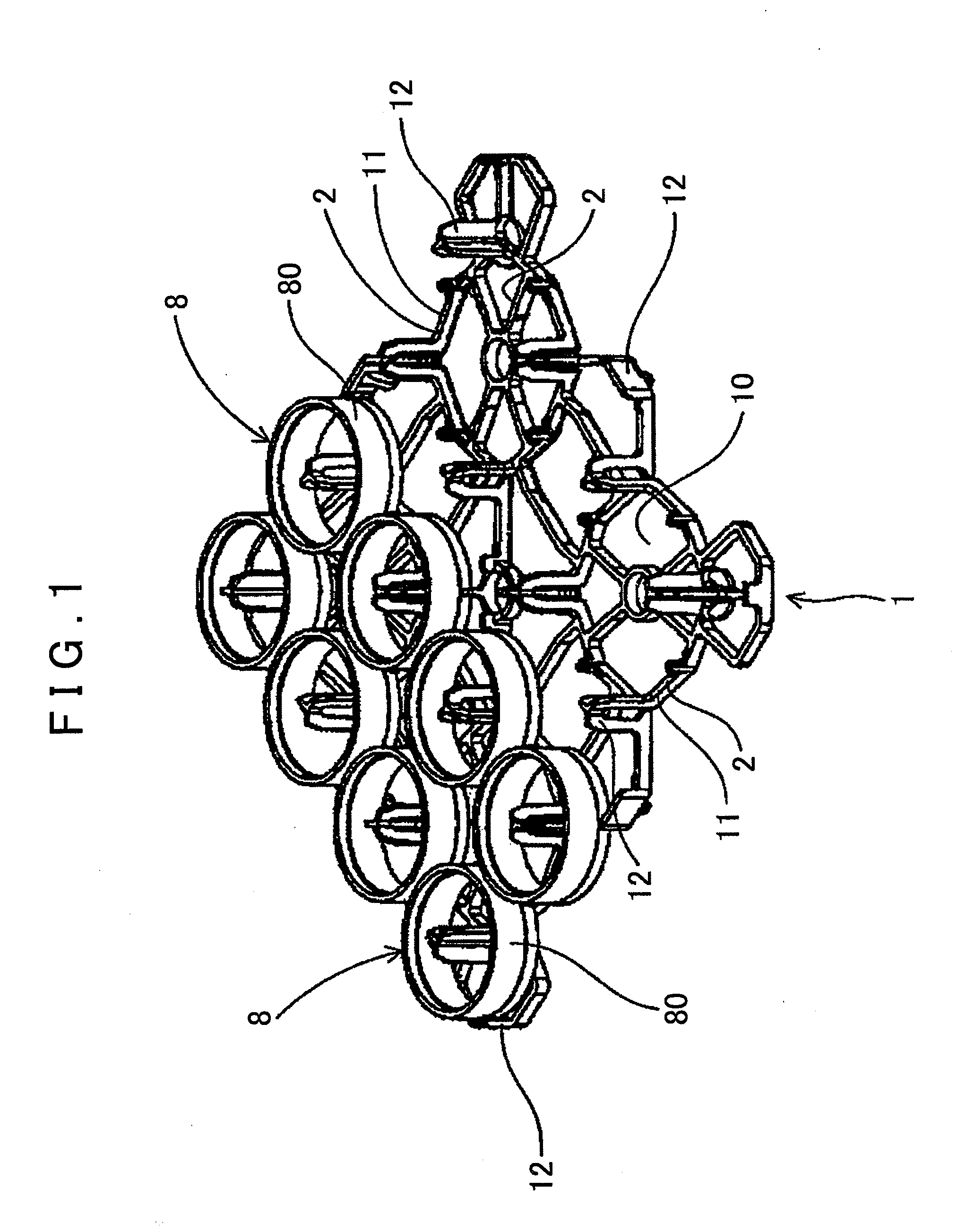
[0038]In this embodiment, a method of heat-treating a ring gear as a workpiece 8 formed of carbon steel in a reduced-pressure atmosphere in which pressure is reduced compared to an atmospheric pressure is taken as an example, and a reduced-pressure heat treatment jig 1 (hereinafter appropriately referred to as the “jig 1”) used for the treatment will also be described.

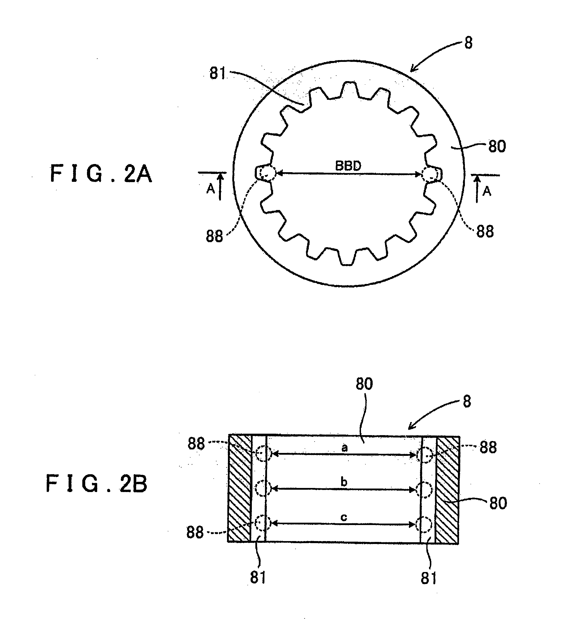
[0039]As shown in FIG. 2, the workpiece 8 of this embodiment is a ring gear having a cylinder-shaped ring section 80, in which spline teeth 81 are formed on an inner circumference surface of the ring section 80. The ring gear is a part incorporated in an automatic transmission (A / T) for an automobile, and is required to have an extremely high standard of dimensional accuracy, including for example roundness.

[0040]As ...

second embodiment

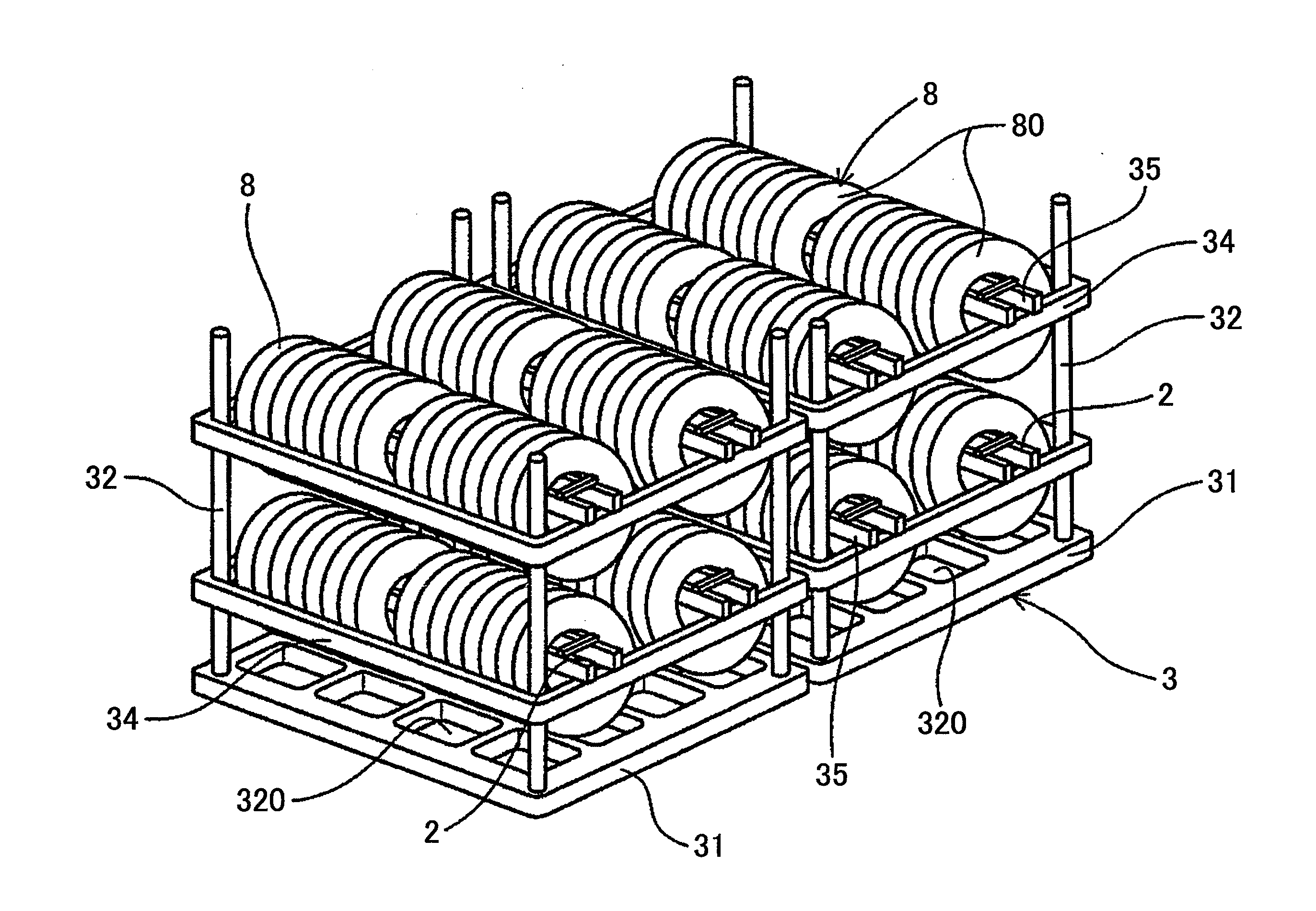
[0053]In this embodiment, a reduced-pressure heat treatment jig 3 (hereinafter appropriately referred to as the “jig 3”) is used instead of the jig 1 of the first embodiment as an example, as shown in FIG. 4. The workpiece 8 and the reduced-pressure carburization treatment are similar to those of the first embodiment.

[0054]As shown in FIG. 4, the jig 3 of this embodiment is a jig formed to support the workpiece 8 with the axis of the workpiece in a horizontal direction in a state such that the workpiece 8 is hung from a hang rack 35, which is a part of the jig 3. As shown in FIG. 4, a bottom plate section 31 of the jig 3 has a skeletal structure in which a number of spaces 320 are provided, so that atmosphere gas can circulate. At the bottom plate section 31, a plurality of pillar sections 32 are set, and it is formed such that the pillar sections 32 supports a side rack 34 and the hang rack 35.

[0055]The feature of this embodiment is that the film 2 similar to that of the first embo...

exemplary embodiment 1

Testing of Exemplary Embodiment 1

[0057]A test for measuring and evaluating a dimensional accuracy of the workpiece 8 after treatment was performed in order to clarify the advantage in the case where the reduced-pressure heat treatment is performed using the jig 1 described in the first embodiment.

[0058]Specifically, a jig of the related art with the same shape but without the film 2 was prepared separate from the jig 1, two charges of the same reduced-pressure carburization treatment as that of the first embodiment were performed, and heat treatment was performed for a total of 336 workpieces 8.

[0059]The evaluation of the dimensional accuracy was performed by a measurement of a so-called “BBD ellipse.” Specifically, as shown in FIGS. 2A and 2B, steel spheres 88 having a predetermined diameter are arranged to contact a concave portion of the spline teeth 81, and the “BBD” which is a dimension obtained by measuring an inner diameter dimension between the opposing steel spheres 88 is d...


PUM

PropertyMeasurementUnit
Pressureaaaaaaaaaa
Temperatureaaaaaaaaaa
Pressureaaaaaaaaaa

Abstract

A reduced-pressure heat treatment jig is used for supporting a workpiece of iron when the workpiece is subjected to heat treatment in a reduced-pressure atmosphere in which pressure is reduced compared to atmospheric pressure. The jig is formed of an iron material and is formed with a film on at least a contact surface with the workpiece, the film being formed of a material which persists during the heat treatment. The film preferably includes a metal oxide having an evaporating temperature higher than the heat treatment temperature in the reduced-pressure atmosphere. The film preferably contains aluminum oxide.

Description

INCORPORATION BY REFERENCE[0001]The disclosure of Japanese Patent Application No. 2007-253191 filed on Sep. 28, 2007 including the specification, drawings and abstract is incorporated herein by reference in its entirety.BACKGROUND OF THE INVENTION[0002]1. Field of the Invention[0003]The present invention relates to a heat treatment jig for supporting a workpiece when a heat treatment is performed under a reduced-pressure atmosphere, and a reduced-pressure heat treatment method using the same.[0004]2. Description of the Related Art[0005]There are cases where various materials formed of an iron material, for example steels such as carbon steel and special steel, are subjected to heat treatment under reduced pressure, for example a reduced-pressure carburization treatment. In these cases, a workpiece formed of the iron material is usually arranged in a heat-treating furnace in a state supported by a heat treatment jig rather than being placed directly in the furnace.[0006]The heat trea...

Claims


Application Information

Patent Timeline
IPC IPC(8): F27D5/00C23C8/22
CPCC21D9/0025C21D9/08C21D9/32C21D1/74C23C2/12C23C2/28C23C8/22C21D9/40C21D1/06C21D1/773
Inventor KATO, SUSUMUSHINKOU, NOZOMUTABATA, MORIYUKITAGUCHI, KEITAOKADA, KAZUAKI
Owner AISIN AW CO LTD
Learn More