Method of manufacturing a magnetite-coated iron powder

a technology of iron powder and magnetite, which is applied in the direction of coating, inorganic material magnetism, transportation and packaging, etc., can solve the problems of difficult difficult to control the thickness of the magnetite, and tend to thin film, so as to achieve easy control of the thickness of the oxide film, improve the purity of the iron particle, and improve the effect of permeability

Inactive Publication Date: 2009-04-02
TAIYO YUDEN KK
View PDF3 Cites 4 Cited by
  • Summary
  • Abstract
  • Description
  • Claims
  • Application Information

AI Technical Summary

Benefits of technology

[0012]The second aspect is identical with the first aspect in that magnetite is formed at a uniform film thickness and the film thickness can be controlled easily but is different from the first aspect in that the iron powder to be coated is formed by pyrolysis of iron pentacarbonyl. Iron pentacarbonyl is pyrolyzed in a reducing atmosphere to precipitate iron particles and then the reaction liquid containing the precipitated iron particles is heated in an oxidizing atmosphere to precipitate magnetite and coat the same on the surface of the previously precipitated iron particles.
[0013]According to the second aspect of the disclosed embodiments of the invention, since magnetite is coated in a state where the iron

Problems solved by technology

However, in the method of heat treating the iron powder thereby oxidizing the surface, since formation of an oxide film proceeds no more after the oxide film is formed over the entire surface, it is difficul

Method used


Image

  • Method of manufacturing a magnetite-coated iron powder
  • Method of manufacturing a magnetite-coated iron powder

Examples


example

Example 1

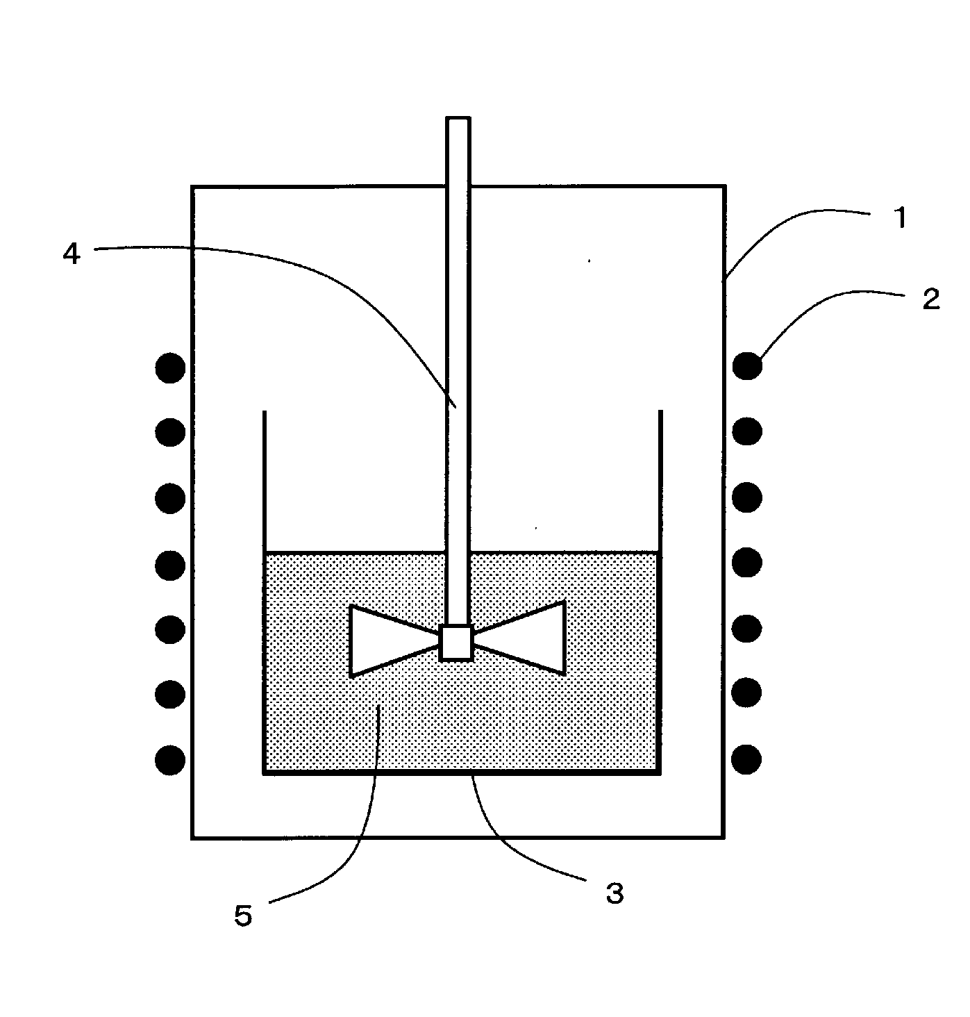
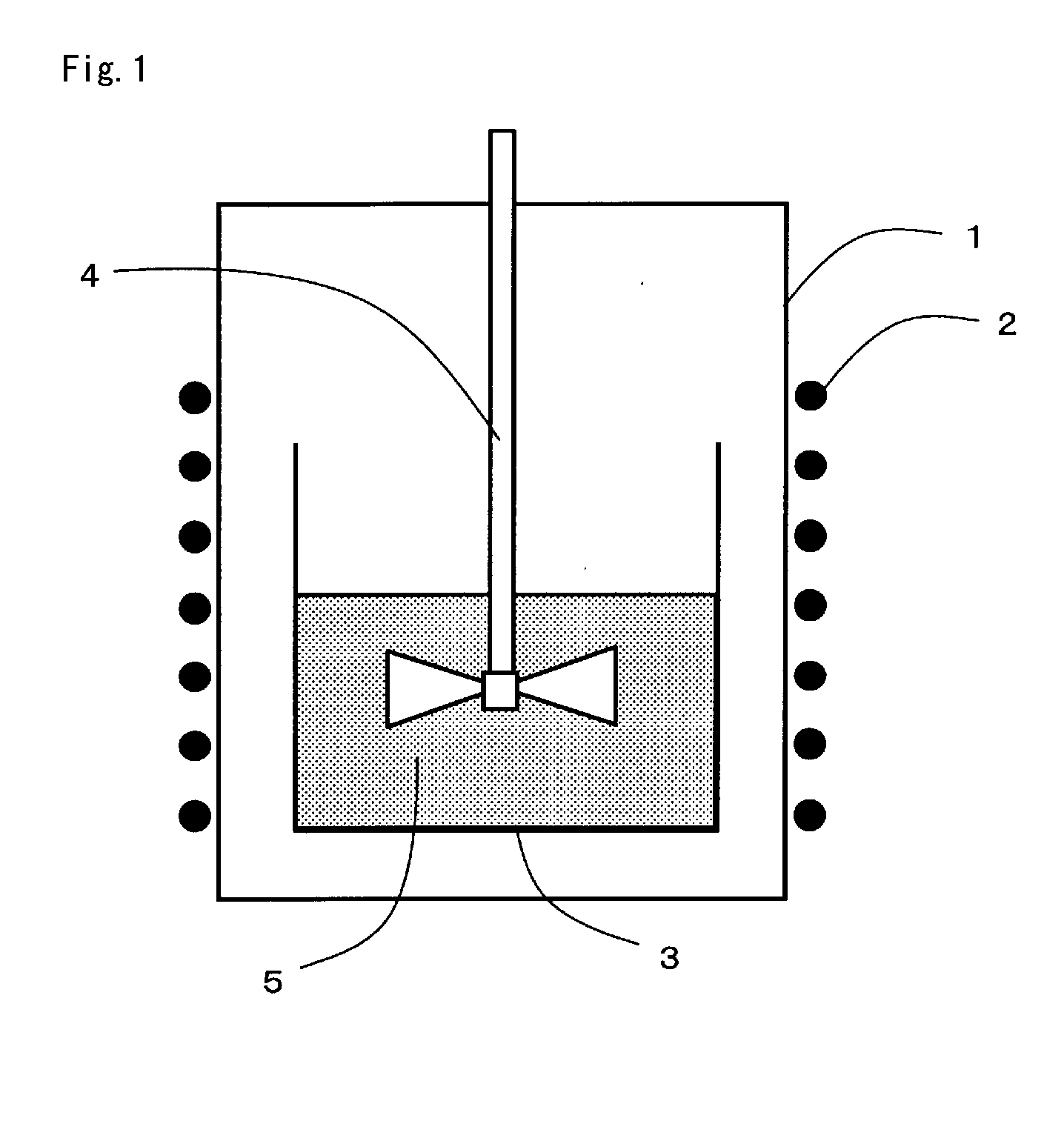
[0030]500 mg of iron pentacarbonyl and 5 ml of decalin were mixed to prepare a reaction liquid. Then, a closed vessel of 4.0 cm inner diameter and 19 cm depth having a rotary blade for stirring was provided, and a glass vessel of 3.5 cm inner diameter and 8.0 cm height was placed as a solution tank in the closed vessel. The reaction liquid described above was contained in the solution tank. Then, 320 mg of an iron powder with an average value of the particle diameter of 3 μm was charged in the solution tank while stirring the reaction liquid by the rotary blade. Then, the cover for the closed vessel was closed to seal the vessel.

[0031]Then, the closed vessel was heated by a heater wound around the periphery thereof to elevate the temperature in the closed vessel to 350° C. Reaction was carried out at 350° C. for 5 hours and, when the temperature was lowered to room temperature, the reaction liquid was taken out. The taken out reaction liquid was filtered through filter pape...

example 2

[0034]500 mg of iron pentacarbonyl and 5 ml of decalin were mixed to prepare a reaction liquid. Then, a closed vessel of 4.0 cm inner diameter and 19 cm depth having a rotary blade for stirring was provided, and a glass vessel of 3.5 cm inner diameter and 8.0 cm height was placed as a solution tank in the closed vessel. The reaction liquid described above was contained in the solution tank. Then, a nitrogen-hydrogen mixed gas comprising 97% nitrogen and 3% hydrogen was filled inside the closed vessel and the cover was closed to seal the vessel.

[0035]Then, the closed vessel was heated by a heater wound around the periphery thereof to elevate the temperature in the closed vessel to 250° C. Reaction was carried out at 250° C. for 5 hours while stirring the reaction liquid by the rotary blade to form 93 mg of an iron powder with an average value of 3 μm for the particle diameter.

[0036]Then, the cover for the closed vessel was opened to replace the nitrogen-hydrogen mixed gas with an atm...


PUM

PropertyMeasurementUnit
Temperatureaaaaaaaaaa
Thicknessaaaaaaaaaa
Volume ratioaaaaaaaaaa

Abstract

A method of manufacturing a magnetite-coated iron powder includes putting an iron powder into a reaction liquid containing iron pentacarbonyl and heating the same in an oxidizing atmosphere, or includes heating a reaction liquid containing iron pentacarbonyl in a reducing atmosphere thereby precipitating iron particles and heating the reaction liquid in which iron particles are precipitated in an oxidizing atmosphere and coating magnetite to the precipitate iron particles.

Description

BACKGROUND OF THE INVENTION[0001]1. Field of the Invention[0002]The present invention provides a method of coating magnetite (Fe3O4) on the surface of an iron powder which can control the film thickness of magnetite easily.[0003]2. Description of the Related Art[0004]In recent years, the operation frequency for circuits forming electronic instruments has been increased to a high frequency region as reaching a GHz level. Therefore, it has been demanded also for electronic parts forming the circuits that they operate normally in a high frequency region. Also for a wire wound type inductor having a magnetic substance core applied with windings, it has been required that the inductor operates normally in the high frequency region. It is necessary that the magnetic substance core used for the wire wound type inductor conforming to high frequency has high saturation magnetization, high magnetic permeability, and high electric resistivity. As the material for forming the magnetic substance...

Claims


Application Information

Patent Timeline
IPC IPC(8): B05D1/00B22F1/16
CPCB22F1/02B22F2999/00H01F1/33B22F1/0088B22F2201/03B22F1/0074B22F1/0085B22F9/30B22F1/16B22F1/145B22F1/142B22F1/107
Inventor KAWANO, KENJIYOGO, TOSHINOBU
Owner TAIYO YUDEN KK
Why Eureka
Try Eureka