Integration of an integrated gasification combined cycle power plant and coal to liquid facility

a gasification and combined cycle technology, applied in the direction of combustible gas production, combustible gas chemical modification, combustible gas purification/modification, etc., can solve the problems of high coal content in these materials, less favorable to electricity generation, shutdown, etc., to achieve the effect of improving production efficiency, scalability, and reliability

Inactive Publication Date: 2009-04-09
RES USA LLC
View PDF4 Cites 8 Cited by
  • Summary
  • Abstract
  • Description
  • Claims
  • Application Information

AI Technical Summary

Benefits of technology

[0011]These and other needs in the art are addressed in an embodiment of an integrated Coal to Liquid and Integrated Gasification Combined Cycle facility described herein. A novel method of combining a CTL fuel plant and an IGCC electrical plant by sharing the systems of coal intake, coal preparation, gas separation, and water units is described herein. This configuration allows the combined facility to offer advantages in efficiency of production, operational flexibility, scalability, and reliability by a multi-path integration of the processing units.

Problems solved by technology

Current and tightening emissions regulations limit the amount of sulfur, oxides of nitrogen, and greenhouse gas emissions, making coals high in these materials less favorable for electricity generation.
Failure to comply with these regulations results in hefty penalties in the form of fines, shutdowns, and limited operations.
Further, upgrading of current coal burning electric generation plants requires substantial investment.
With increased awareness of environmental issues such as global warming, and greenhouse gases, this trend is predicted to continue, potentially making coal-burning plants unfavorable and expensive to operate.
The limitations of these components dictate the upper range of the steam temperatures, and therefore limit efficiency of electric power production.
The current costs of material, process, capital, and infrastructure make individual investments in these processes expensive rendering them unfavorable for development.
However, it is recognized that provided a singular source of syngas to operate a plurality of clean coal plants is disadvantageous for operational flexibility, the capacity to scale output to demand, and maintain production during maintenance, or in the case of a device failure.

Method used


Image

  • Integration of an integrated gasification combined cycle power plant and coal to liquid facility
  • Integration of an integrated gasification combined cycle power plant and coal to liquid facility
  • Integration of an integrated gasification combined cycle power plant and coal to liquid facility

Examples


Embodiment Construction

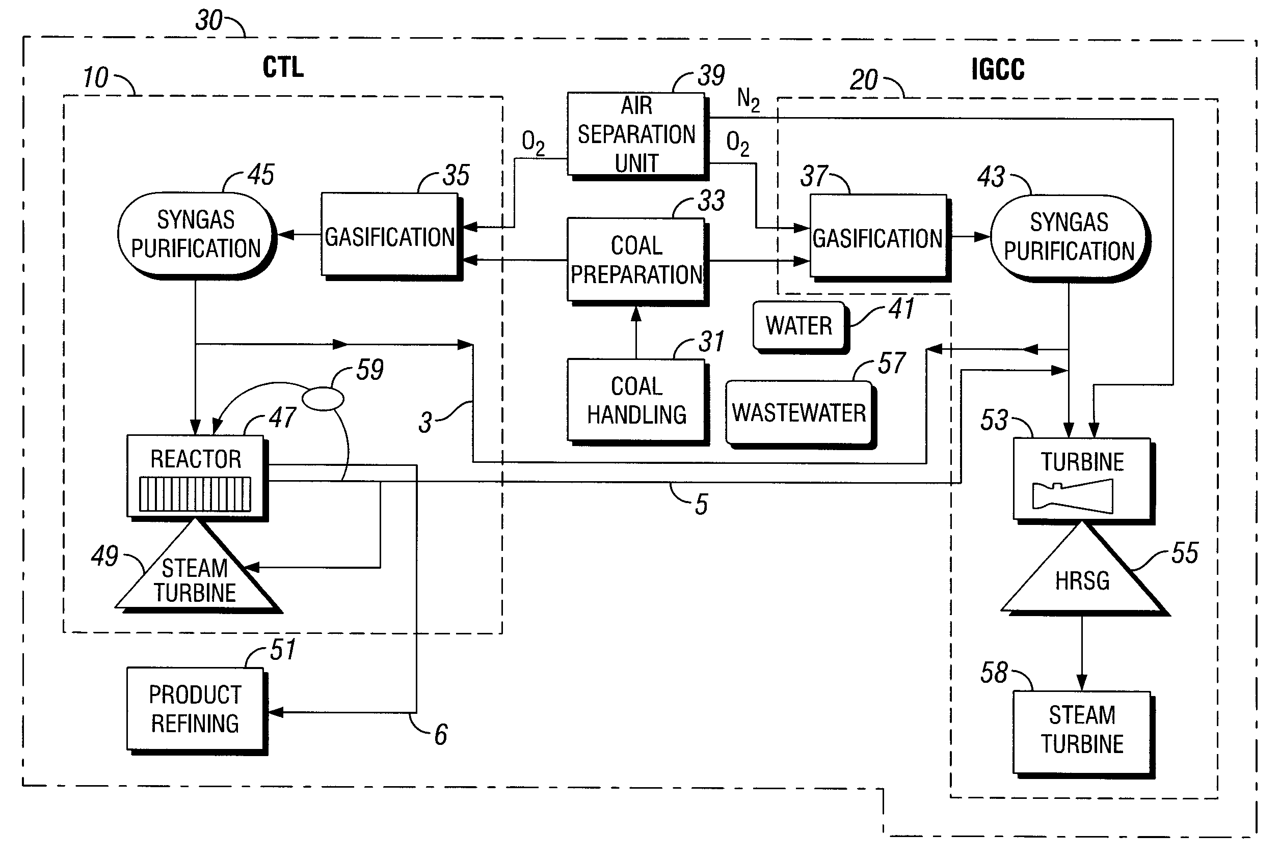
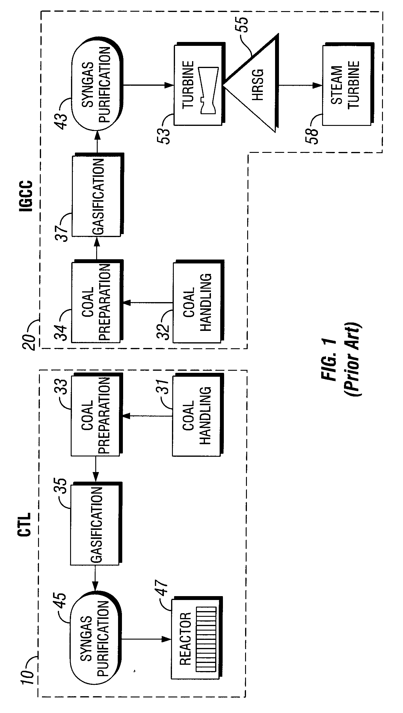
[0024]Referring now to FIG. 1, that illustrates the components of non-integrated facilities for coal to liquid (CTL) fuel production 10 and an integrated gasification combined cycle (IGCC) power plant 20 in a side-by-side manner. CTL facility 10 comprises a Fischer-Tropsch Reactor 47 for the production of liquid hydrocarbons. IGCC facility comprises IGCC gas turbine 53 for the combustion of syngas to produce electricity. Further, FIG. 1 illustrates the parallel or similar coal processing steps used in both the facilities. For example without limitation, these may include coal handling, 31, 32 coal preparation 33, 34 and gasifier (gasification unit) 35, 37, and syngas purifier 43, 45. Additionally, both facilities may comprise a process for gas treatment, water treatment, wastewater treatment, waste removal and / or similar processes understood by one skilled in the art.

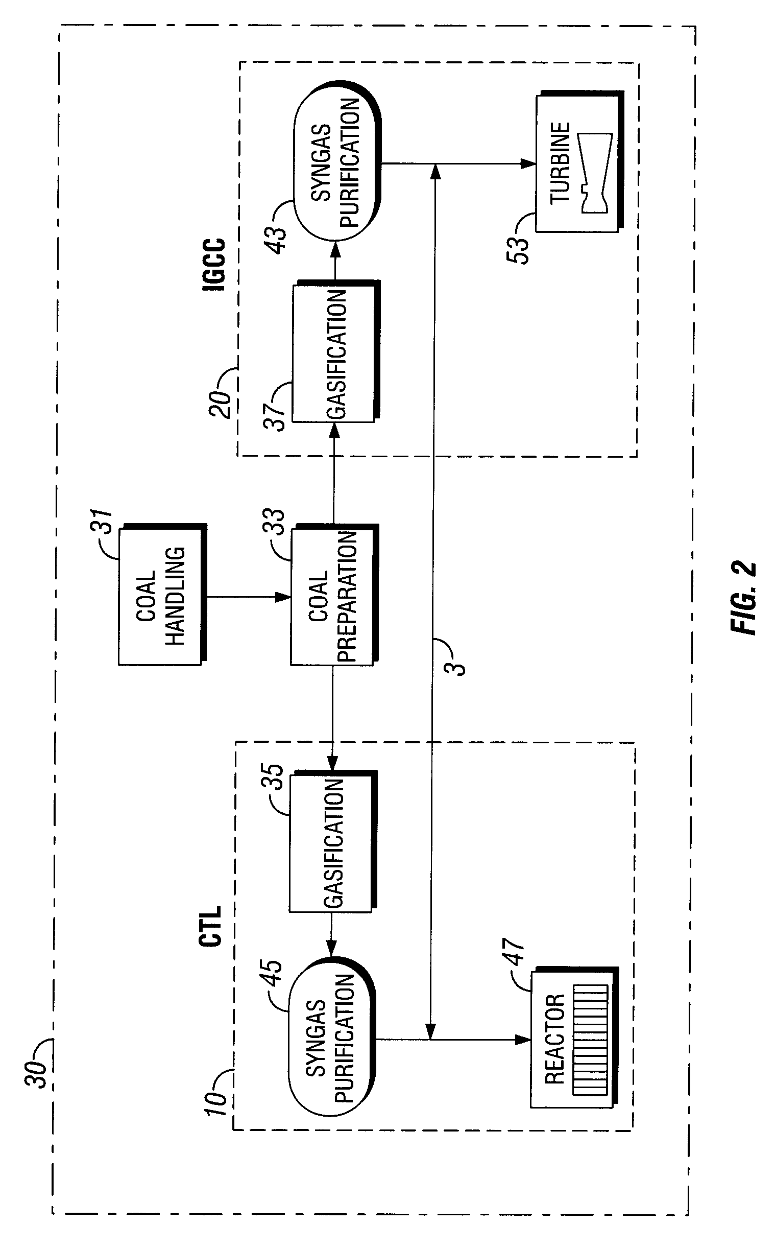
[0025]In an embodiment, the disclosed process comprises a multi-path means to integrate the CTL 10 and IGCC 20 facili...


PUM

PropertyMeasurementUnit
liquidaaaaaaaaaa
electrical energyaaaaaaaaaa
temperaturesaaaaaaaaaa

Abstract

A novel method of combining the CTL fuel plant and IGCC electrical plant by sharing the systems of coal intake, coal preparation, gas separation, and water units is described herein. This configuration allows for the combined facility to offer advantages in efficiencies of production, operational flexibility, scalability, and reliability by a multi-path integration of the processing units.

Description

[0001]This application claims the benefit under 35 U.S.C. § 119(e) of U.S. Provisional Patent Application No. 60 / 972,450, filed Sep. 14, 2007, and Application No. 60 / 972,522, filed Sep. 14, 2007, the disclosures of which are incorporated herein by reference in their entirety for all purposes.BACKGROUND[0002]1. Field of the Invention[0003]This invention relates generally to the field of clean coal energy production. More specifically, the invention relates to a method of combining two clean coal processes into a single facility.[0004]2. Background of the Invention[0005]Natural gas, coal deposits, and biomass are abundant energy sources that often serve as fuel for power generation. The United States has significant known reserves of coal, and coal currently burned for power generation represents only a fraction of the total deposits that are available. This coal used for power satisfies approximately one-half of the electrical energy demand of the United States. Current and tightenin...

Claims


Application Information

Patent Timeline
Patent Type & Authority Applications(United States)
IPC IPC(8): C10J3/00C10G2/00
CPCC10G2/32C10J2300/0903C10J2300/093C10J2300/0959C10J2300/0973C10J2300/165Y02E20/16C10J2300/1671C10J2300/1675C10J2300/1678F02C3/28Y02E20/18C10J2300/1659
Inventor REGNERY, JOSEPH A.SHEPPARD, RICHARD O.
Owner RES USA LLC
Why Eureka
Try Eureka