Exhaust Gas-Discharging Device of Vehicle

a technology of exhaust gas and discharge device, which is applied in the direction of machines/engines, mechanical equipment, transportation and packaging, etc., can solve the problems of reducing the output of the engine by 5% to 10%, affecting the efficiency of the engine, so as to prevent the backflow of exhaust gas and prevent the effect of back pressur

Inactive Publication Date: 2009-04-09
KIM SOO WON
View PDF25 Cites 7 Cited by
  • Summary
  • Abstract
  • Description
  • Claims
  • Application Information

AI Technical Summary

Benefits of technology

[0029]As described above, in the present invention, the exhaust gas discharge device is additionally coupled to the tail pipe of a silencer, through which exhaust gas is discharged outside. Therefore, the present invention can be easily applied to an existing vehicle without changing the construction of the existing exhaust system. Furthermore, exhaust gas is rapidly discharged by a venturi phenomenon, and outside air, which is drawn into a chamber of the exhaust gas discharge device and is circulated and discharged outside the vehicle, prevents the backflow of exhaust gas and thus prevents back pressure, thereby improving exhaust efficiency and enhancing the output of the engine. In addition, the present invention is designed such that the structures of the outside air discharge nozzle and the backflow inlet port can be changed, so that design of the chamber for forming a low pressure state therein can be easily conducted. As well, the present invention has a solid structure, thus markedly increasing the durability thereof, and can be applied to an existing vehicle without changing the construction of the existing silencer, thus having superior intercompatibility. Moreover, the present invention markedly reduces the backflow of exhaust gas, thus preventing combustion residue, such as carbon, from being deposited, thus extending the lifetime of the engine, and maintaining components of the exhaust system, including an expensive gas purification device, clear and in a normal state, thereby extending the lifetime of the components.
[0030]Meanwhile, although the exhaust gas discharge device of the present invention is illustrated as being used in vehicles, it will be easily appreciated that the present invention can be applied to any mechanism using an internal-combustion engine provided with a silencer having a tail pipe.

Problems solved by technology

However, in the exhaust process, because exhaust gas is discharged outside the vehicle via an exhaust manifold, a gas purification device comprising a catalyst, and a silencer, there is a relatively large amount of resistance to the discharge air flow.
However, such a silencer has a disadvantage in that exhaust gas is not smoothly discharged from the engine due to air resistance, thus reducing the output of the engine by 5% to 10%.
However, this technique is disadvantageous in that the streamline-shaped body has a relatively large and complex structure affecting the installation thereof, and, when the vehicle is stopped or travels at a relatively low speed, because rapid air flow cannot be induced, the narrow discharge passage interferes somewhat with the discharge of exhaust gas.
Therefore, it is very difficult to use this technique in practice.
However, there is a problem in that the blade serves as a source of some resistance that interferes with the flow of exhaust gas, and thus it cannot be used in practice.
However, it is difficult to rapidly and smoothly discharge exhaust gas using only vortexes generated in the exhaust gas.
As such, the efficiency of the device is very low.
However, in this technique, because the duct is provided on the front pipe of the silencer, which serves to reduce exhaust noise, exhaust noise is transferred outside through the duct.
Moreover, when the vehicle accelerates, the degree of opening of the valve is increased, and thus exhaust noise becomes severe.
Furthermore, because exhaust gas is discharged through the sub duct, which has low air resistance compared to the interior of the silencer, outside air cannot be smoothly supplied into the duct because of the resistance.
Therefore, it is also difficult to use this technique in practice.
In addition, in this technique, because outside air is drawn into an inlet of the silencer, air resistance still occurs in the silencer, and thus it is not useful for increasing the exhaust rate.
As well, the device is provided with an air regulating damper, which is operated in conjunction with the throttle valve of the engine, so that there is a disadvantage in that the structure thereof is complex.
Because outside air, drawn into the duct, passes through the silencer, foreign substances (dust, sand, etc.), which have been contained in the outside air, are deposited in the silencer, thus deteriorating the performance of the silencer.
However, there is a disadvantage in that, when the vehicle is stopped or travels at a low speed, the effect of this technique is markedly reduced.

Method used


Image

  • Exhaust Gas-Discharging Device of Vehicle
  • Exhaust Gas-Discharging Device of Vehicle
  • Exhaust Gas-Discharging Device of Vehicle

Examples


Embodiment Construction

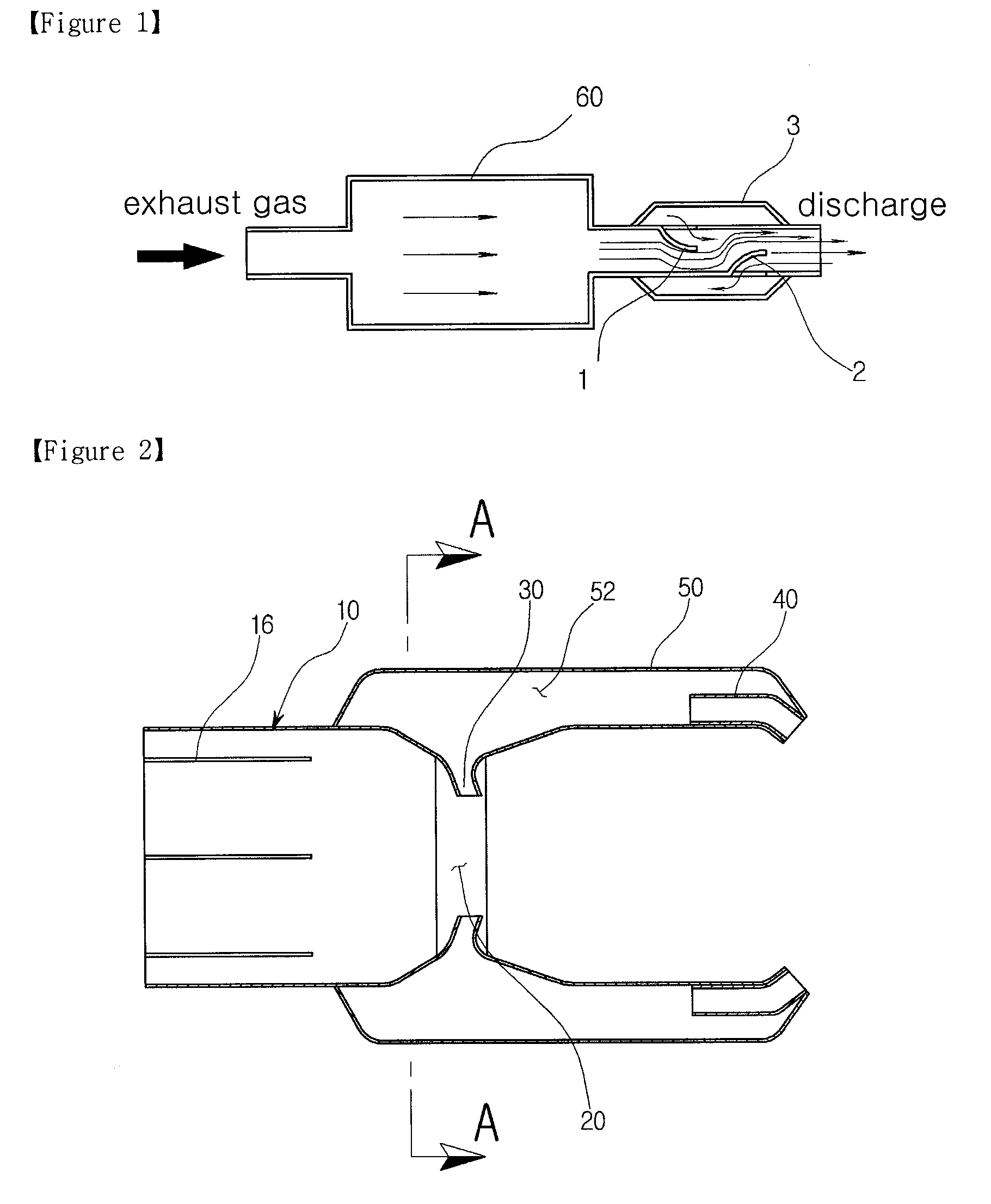
[0056]The present invention, having the above-mentioned construction and operation may be modified, as shown in FIG. 5.

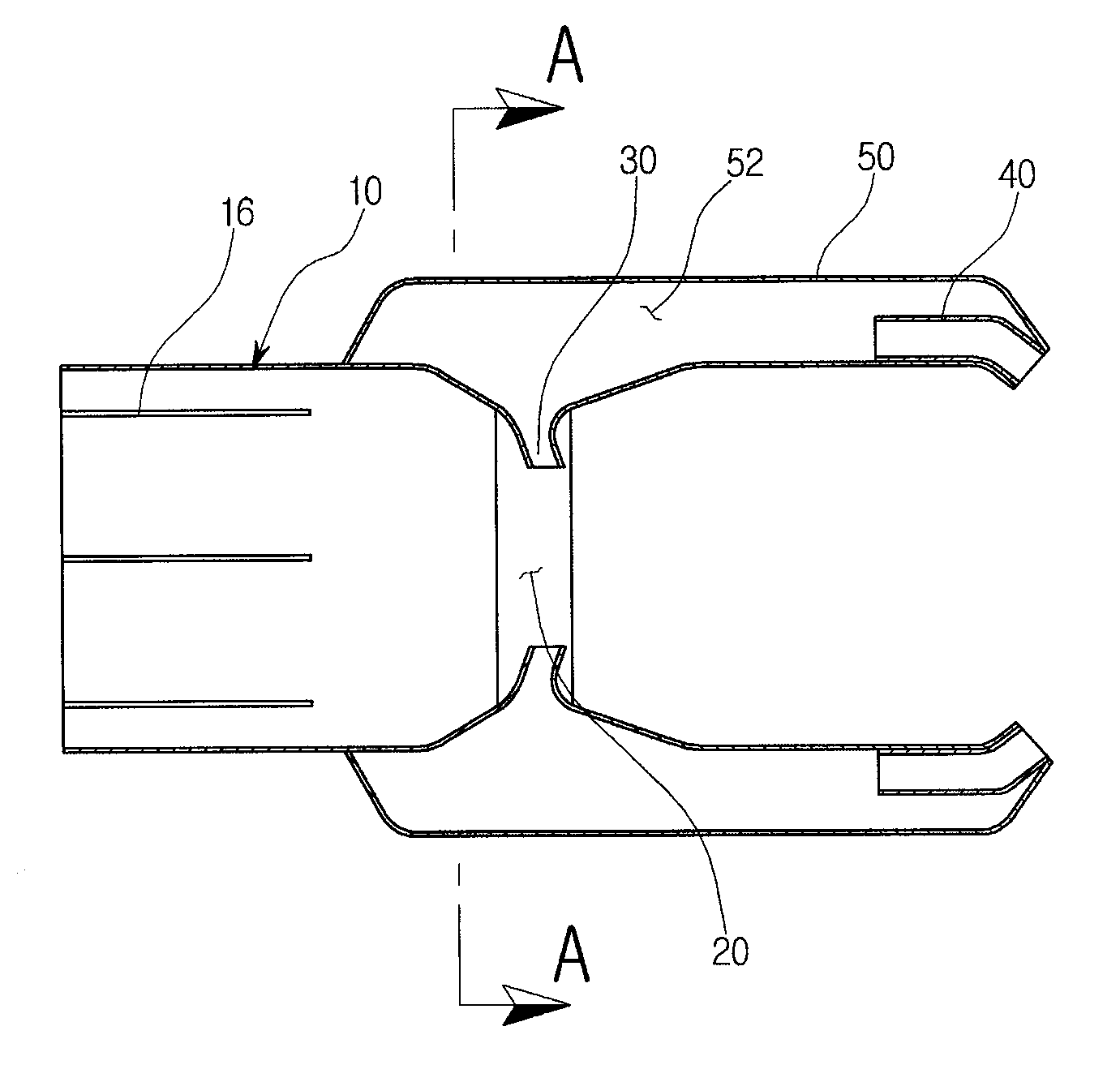
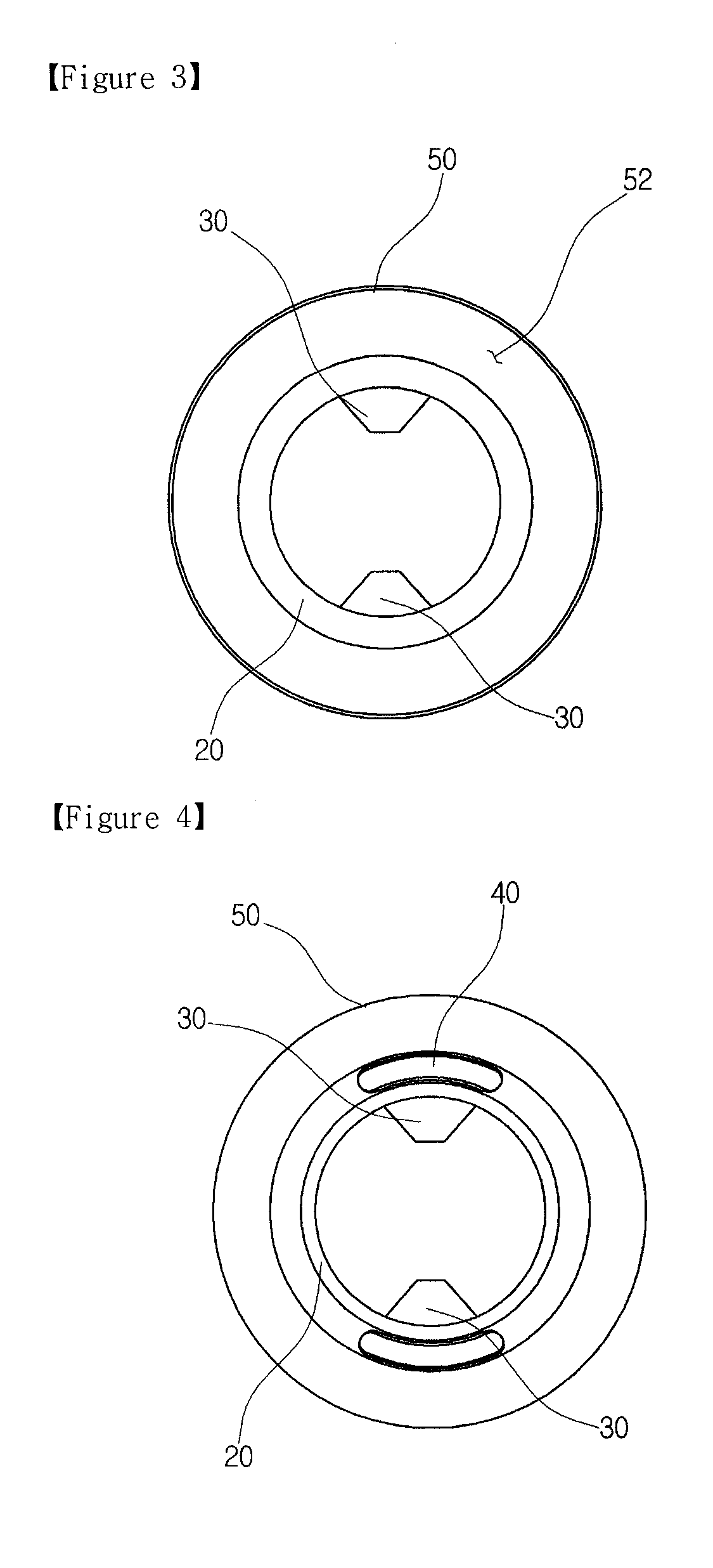
[0057]In detail, in the embodiment of FIG. 5, the air circulation operation, using a venturi passage 20 and a chamber 52, is the same as that of the prior embodiment. However, unlike the prior embodiment, the embodiment of FIG. 5 further includes a subsidiary venturi passage tube 22, which is provided in the venturi passage 20, so that outside air, which has passed through outside air discharge nozzles 30, is discharged through the subsidiary venturi passage tube 22. Thus, the discharge speed of exhaust gas, which is increased through the venturi passage 20, is further increased by the subsidiary venturi passage tube 22 (see, FIG. 8).

[0058]Each outside air discharge nozzle 30 comprises an inclined pipe, the diameter of which is reduced from the inlet end thereof, adjacent to the chamber 52, to the discharge end thereof, thus serving to increase the acceleration of d...


PUM


Abstract

An exhaust gas discharge device for vehicles is disclosed. The exhaust gas discharge device of the present invention includes an extension pipe (10), which is fitted over a tail pipe of a silencer of a vehicle. A venturi passage (20) is defined in an exhaust gas inlet end of the extension pipe to increase a flow speed of the exhaust gas. The exhaust gas discharge device further includes an outside air discharge nozzle (30), which extends into the venturi passage, a backflow inlet port (40), which is provided in an exhaust gas outlet end of the extension pipe to guide outside air, and a cover (50), which defines therein a chamber, through which the backflow inlet port communicates with the outside air discharge nozzle. Thus, the present invention restrains backflow of exhaust gas using the flow of outside air, thus preventing back pressure, and rapidly discharging the exhaust gas, thereby enhancing the output of the engine.

Description

TECHNICAL FIELD[0001]The present invention relates, in general, to exhaust gas discharge devices for discharging exhaust gas, used in internal-combustion engines for vehicles, and more particularly, to an exhaust gas discharge device for vehicles which is coupled to a tail pipe of a silencer provided in an exhaust gas discharge path of a vehicle and is constructed such that the backflow of exhaust gas is restrained by the flow of air, thus preventing back pressure, and rapidly discharging the exhaust gas, thereby reducing fuel consumption and enhancing the output of the engine.BACKGROUND ART[0002]As well known to those skilled in the art, in an internal-combustion engine of a vehicle, power is obtained through a four-stroke cycle including an intake stroke, a compression stroke, an explosion stroke and an exhaust stroke.[0003]With regard to the flow of gas (intake air and discharge air) during the strokes of the engine, in the intake process, gas is drawn into the engine after passi...

Claims


Application Information

Patent Timeline
Patent Type & Authority Applications(United States)
IPC IPC(8): F01N7/20F01N13/20F01N13/08
CPCF01N13/082F01N2260/06F01N13/20B60R11/0241B60R2011/0085H02J7/14H04B1/3827
Inventor KIM, SOO WON
Owner KIM SOO WON
Why Eureka
Try Eureka