
Waste energy conversion system

a technology of waste energy and conversion system, which is applied in the direction of waste based fuel, combustion types, lighting and heating apparatus, etc., can solve the problems of toxic emissions, and waste to energy system is not cost-effectiv

Inactive Publication Date: 2009-04-09
INFOSCITEX
View PDF19 Cites 45 Cited by
  • Summary
  • Abstract
  • Description
  • Claims
  • Application Information

AI Technical Summary

Benefits of technology

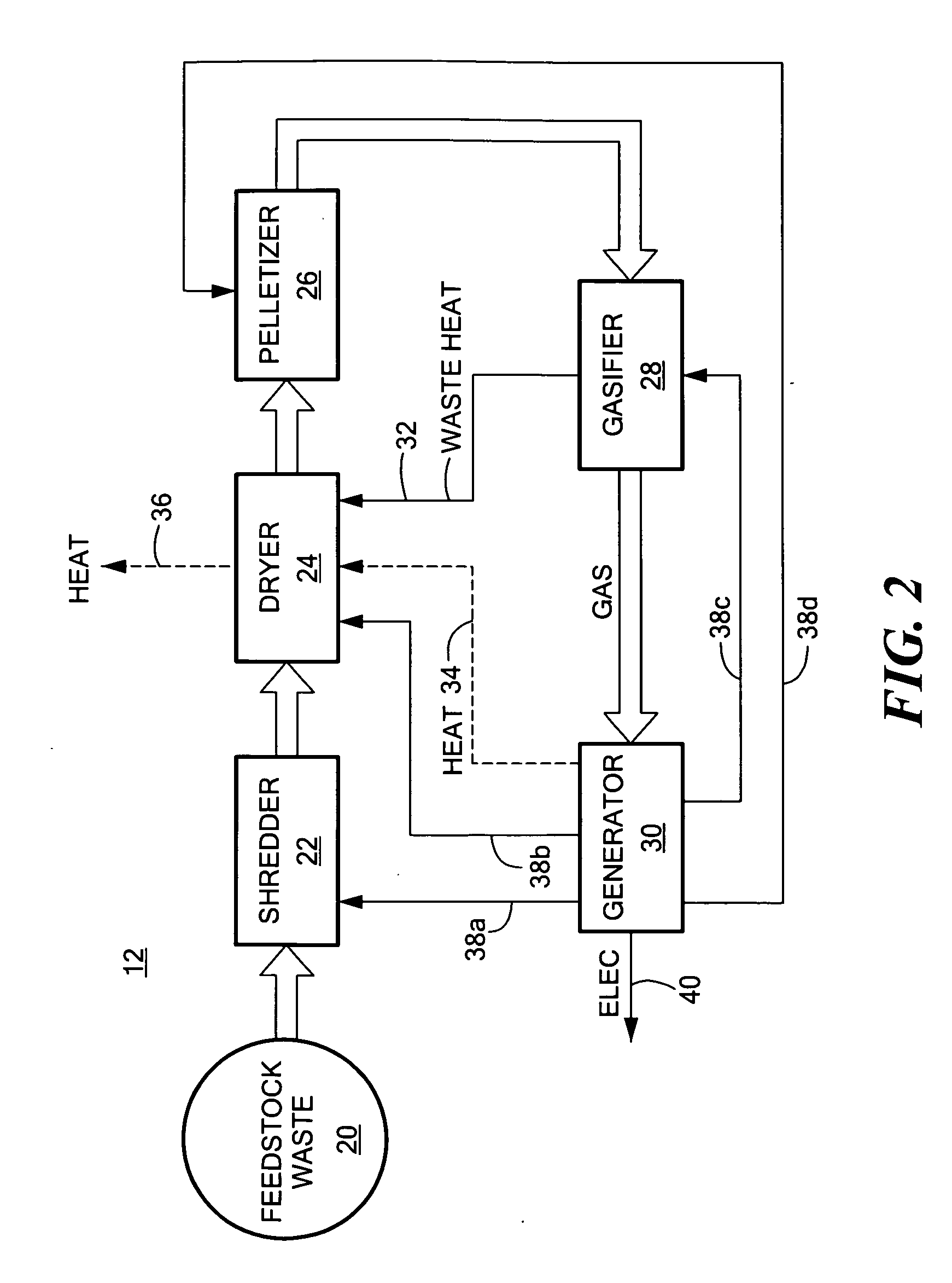
"The invention is a waste processing system and method that is modular, self-powered, cost-efficient, and produces high-quality fuel pellets. It can be used on-site at food service facilities and is not an environmental burden. The system includes a shredder, dryer, pelletizer, gasifier, and generator. The method involves shredding the waste, drying it, using a densifier to produce gas and waste heat, and using the waste heat to dry the shredded waste. The generated electricity is used to power the shredder, dryer, pelletizer, and gasifier. The system is efficient, cost-effective, and produces high-quality fuel pellets."

Problems solved by technology

Sorting of the waste to produce viable fuel pellets is a major problem since municipal waste includes metal, wood products, chemicals, glass, and a variety of other materials.
Often, the waste-to-energy system is not cost-effective due to the sorting required and the energy draw of the various components of the system.
Toxic emissions may be produced and the burning process generates undesirable ash which may be hazardous.
Production rates near the rated capacity of the pellet mill were not achievable.
Oversized pieces and stringy components of the shredded waste frequently jammed the mill and dies while press wheels wore out at faster rates than desired.
Waste plastic film in the feedstock caused fracture of the pellets into shorter lengths.
Physical degradation of the pellets to smaller pellets and fine particles as a result of conventional handling methods was a common problem.
In addition, food waste and RDF has not been densified into fuel pellets because of the adverse effects of high moisture content on the integrity of the fuel pellets.
Despite the numerous prior art regarding waste-to-energy conversion systems, the problems noted above remain.
Chapter 8 of the above referenced book concludes that commercial experiences with waste-to-energy systems “have not been good.”

Method used


Image

  • Waste energy conversion system
  • Waste energy conversion system
  • Waste energy conversion system

Examples


example 1

[0061]A variety of commercially-available process equipment was evaluated for use in the solid waste preprocessing unit. Experimental trials were run to assess the suitability of candidate equipment for use as-is or with modification in the preprocessing unit. A waste shredder followed by a rotary drum pellet mill was found to produce pellets of good quality and preferred size, without exceeding a parasitic energy loss target of less than 10 percent of the gross energy content of the feed waste stream. The pellets were evaluated in a small modular biopower downdraft gasifier system for their ability to make a high quality synthesis producer gas to produce heat and / or generate electricity.

[0062]Simulated waste streams, derived from Meals-Ready to Eat (MREs), were formulated according to the Force Provider Training Module (Fort Polk) with uncooked food. Table 1 shows the waste composition that was used in the solid waste pre-processing unit. Cardboard and paper were added to the MREs ...

example 2

[0065]Other shredders were evaluated, specifically those used to process hospital and plastic waste. A rotary waste shredder was used to shred stimulant encampment waste.

[0066]Shredder 22, FIGS. 3-4 incorporates hydraulic ram 50 that pushes material against a rotating cutter drum 52 that is driven by an electric motor. Material that is smaller than the screen 54 apertures fall to a collection area below, where it is pushed forward with an auger to a conveyor.

[0067]Two cases of MREs (˜12 pounds, without the magnesium heater packs) were processed for evaluation. One case was loaded into a rotary waste grinder, outfitted with a 0.5″ aperture screen, while the other case was shredded with a 1.0 inch aperture screen using the same machine. Observations were that the equipment handled the material well, and the waste was more homogenous than what was produced with the two-stage shredder. Additionally, the tool cut through thin plastic film with no difficulty, and no long stringy waste was...

example 3

[0071]An initial batch of shredded waste (100 lbs) was processed for pelletization using a roller press. FIG. 7 is a schematic view of a roller press 76 that was used in the test program. Material 60 from feed hopper 62 is supplied into the roll nip with a horizontal screw 64 driven by a variable speed drive 66. Material to be processed is placed into the feed hopper 62 from where it flows into the screw at the feed inlet. The material is then compacted between two rolls 64a and 64b which are cantilevered on the end of shafts outside bearing blocks 68. The rolls are also driven by a variable speed drive. A fully adjustable hydraulic system 70 provides the force holding the rolls together.

[0072]The exit stream from the roll press is a moderately densified sheet of waste. The final densification operation involves passage through briquetting rolls to form the solid waste-based fuel product. The waste will leave these stages having the desired dimensions and density.


PUM


Abstract

An on-site modular method and system for processing waste typically including food from a food services facility. The waste is processed in a size reduction unit and subsequently dried in a dryer. The dried shredded waste is processed to produce densified pellets. The food binds the non-food waste in the pellets. The pellets are burned in a thermal conversion unit to produce a gas and waste heat. The waste heat is directed to the dryer for use therein. The gas is fed to a generator or turbine to produce electricity. A portion of the electricity produced is used to energize the process.

Description

RELATED APPLICATIONS[0001]The subject invention claims the benefit of and priority to U.S. Provisional Application No. 60 / 998,153, filed Oct. 9, 2007 which is incorporated herein by reference.GOVERNMENT RIGHTS[0002]Certain aspects of the subject invention resulted, at least in part, from U.S. Government funding under U.S. Army Contract Nos. W911NF-06-C-0035; W911NF-06-C-0090; W56 HZV-05-C-0012; W56 HZV-05-C-0661; and W91B9472000385. The U.S. Government may have certain rights in the subject invention.FIELD OF THE INVENTION[0003]This subject invention relates to waste-to-energy conversion systems.BACKGROUND OF THE INVENTION[0004]Municipal waste is typically collected and transported to a landfill. Given the shortage of landfill sites, some effort has been made to recycle certain components of the waste. The waste is also sometimes burned. The waste is also sometimes thermally decomposed to produce electricity and / or generate heat. U.S. Pat. No. 7,252,691 incorporated herein by this r...

Claims


Application Information

Patent Timeline
Patent Type & Authority Applications(United States)
IPC IPC(8): F23G5/027
CPCF23G5/006F23G5/02F23G2201/10F23G2201/303F23G2201/40F23G2201/80Y02E50/30F23G2203/70F23G2206/10F23G2206/203F23G2900/50206Y02E20/12F23G2203/60
Inventor GOLD, HARRISCUSHMAN, BARRY MICHAELRUBIN, LESLIE S.OCNOS, GREGORYMULLIGAN, ROBERT F.YOUNG, MATTHEW J.
Owner INFOSCITEX
Learn More