Rotor with a thermal barrier and a motor with such a rotor

a thermal barrier and rotor technology, applied in the direction of dynamo-electric machines, electrical apparatus, magnetic circuits, etc., can solve the problems of high price of more heat resistant magnets and inappropriate start-up characteristics of synchronous motors, and achieve the effect of improving the magnetic field of the magnet, facilitating the creation of air stream through the rotor, and improving the cooling of the magnets

Inactive Publication Date: 2009-04-09
DANFOSS COMPRESSORS
View PDF7 Cites 9 Cited by
  • Summary
  • Abstract
  • Description
  • Claims
  • Application Information

AI Technical Summary

Benefits of technology

[0013]If the thermal barrier is an air gap, the air may be enclosed in a sealed cavity whereby exchange with air of the ambient space is prevented. Alternatively, the air gap is in fluid communication with ambient space via openings in at least one of the end faces. If the air gap forms an opening in both of the end faces, the air passage extending between the openings may extend linearly in the axial direction of the rotor or the passages may be helically coiled around the centre axis. This may facilitate creation of an air stream through the rotor during rotation of the rotor around the centre axis. In that way, the exchange of air in the passages may improve cooling of the magnets further.
[0014]The rotor typically comprises a centre opening in which a crank shaft is located. Since the magnets typically are positioned deep below the rotor surface, close to the centre opening, it may improve the magnetic field from the magnets if the crank shaft has magnetic conductive characteristics.

Problems solved by technology

In certain applications, however, the synchronous motor has an inappropriate start-up characteristic.
More heat resistant magnets are expensive.

Method used


Image

  • Rotor with a thermal barrier and a motor with such a rotor
  • Rotor with a thermal barrier and a motor with such a rotor
  • Rotor with a thermal barrier and a motor with such a rotor

Examples


Embodiment Construction

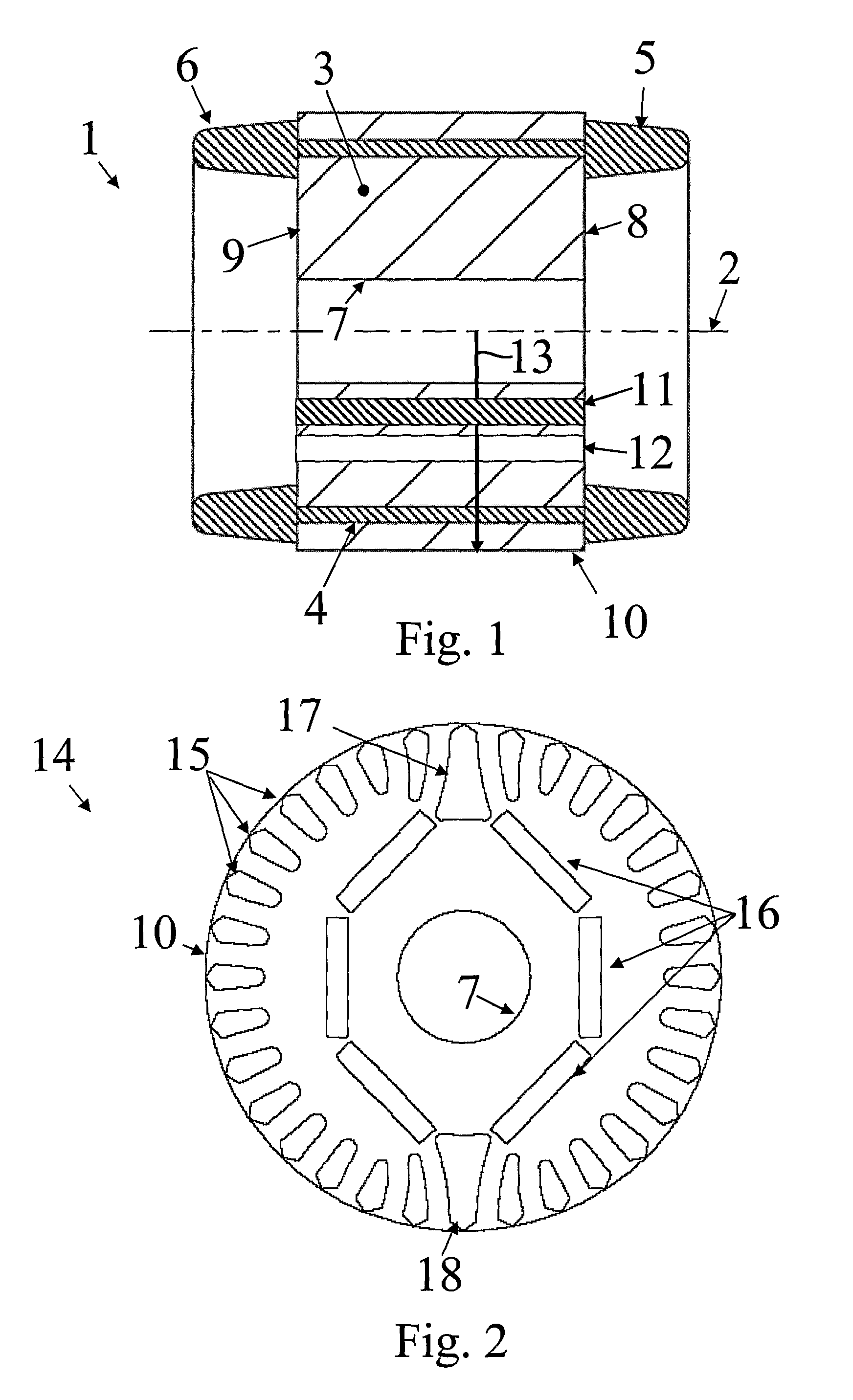
[0033]FIG. 1 illustrates a cross-section of a squirrel cage rotor 1 which is adapted for rotation around a centre axis 2. The rotor 1 comprises a core 3 made from magnetically conductive metal plates which are shown in FIG. 2. The plates are stacked and joined to form the core 3. The core comprises a squirrel cage winding 4 comprising a plurality of conductive bars which extend axially between short circuit rings 5, 6. The rotor comprises an internal bearing surface 7 in which a crank shaft (not shown) is inserted. The end faces 8, 9 of the rotor may form openings into ventilation gaps and may further form openings into cavities in which the magnets are located. The end faces may further form openings into the thermal barriers. The peripheral rim 10 is circular in a cross-section perpendicular to the centre axis 2. The rotor comprises plurality of circumferentially space magnets 11 and corresponding thermal barriers 12. Only one magnet and one thermal barrier is visible in the cross...


PUM


Abstract

The invention provides an electrical line-start motor comprising with a stator and a squirrel cage rotor adapted for rotation around a centre axis. The rotor comprises a squirrel cage winding in which a current is induced by corresponding windings of the stator, and a set of permanent magnets. To protect the magnets from excessive heat, the rotor comprises thermal barriers e.g. in the form of cavities located between the squirrel cage winding of the rotor and the magnets. Due to the thermal barriers, the thermal conductivity in a path between the windings and the magnets are reduced and the magnets are protected.

Description

CROSS REFERENCE TO RELATED APPLICATIONS[0001]This application is entitled to the benefit of and incorporates by reference essential subject matter disclosed in International Patent Application No. PCT / DE2007 / 000433 filed on Mar. 2, 2007 and Danish Patent Application No. PA 2006 00302 filed Mar. 2, 2006.TECHNICAL FIELD[0002]The invention relates to a rotor and an electrical line-start motor comprising a stator with a stator winding and a squirrel cage rotor adapted for rotation around a centre axis. The rotor comprises a core with a set of longitudinally extending windings which are electrically connected by at least one short-circuit ring, and at least one permanent magnet is located in a cavity of the rotor.BACKGROUND OF THE INVENTION[0003]In one type of commonly used electrical motors, a stator comprises a stator winding or several windings in which an electrical field creates a rotating magnetic field. Inside, or circumferentially outside the stator, a rotor is rotationally attac...

Claims


Application Information

Patent Timeline
Patent Type & Authority Applications(United States)
IPC IPC(8): H02K9/00H02K9/02
CPCH02K1/276H02K21/46H02K1/32
Inventor WEIHRAUCH, NIELS CHRISTIAN
Owner DANFOSS COMPRESSORS
Why Eureka
Try Eureka