
System and methods for thick specimen imaging using a microscope based tissue sectioning device

a tissue sectioning device and microscope technology, applied in the field of system and methods for imaging of thick specimens using a microscope based tissue sectioning device, can solve the problems of difficult or impossible to describe the relationships of intact specimens within microscopes, and the resolution of structures may be viewed at the limit of light scattering, so as to achieve accurate imaging and sectioning

Inactive Publication Date: 2009-04-09
PRESIDENT & FELLOWS OF HARVARD COLLEGE
View PDF4 Cites 80 Cited by
  • Summary
  • Abstract
  • Description
  • Claims
  • Application Information

AI Technical Summary

Benefits of technology

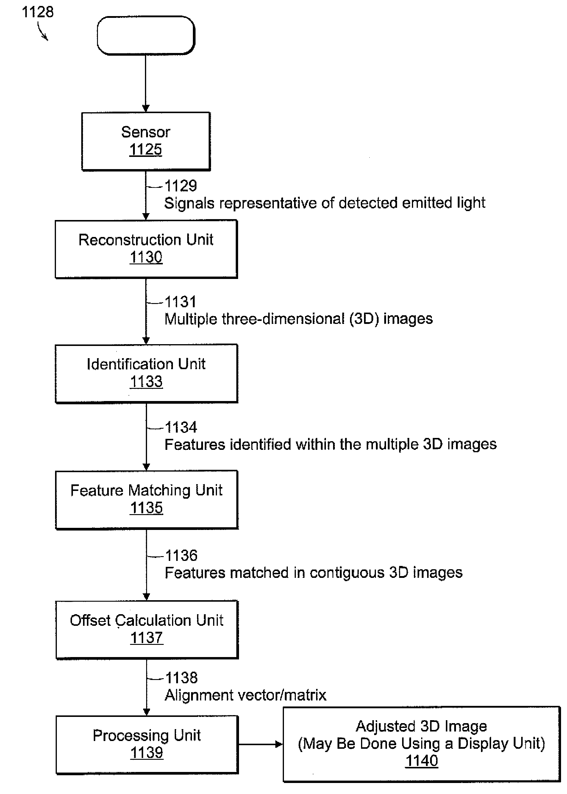
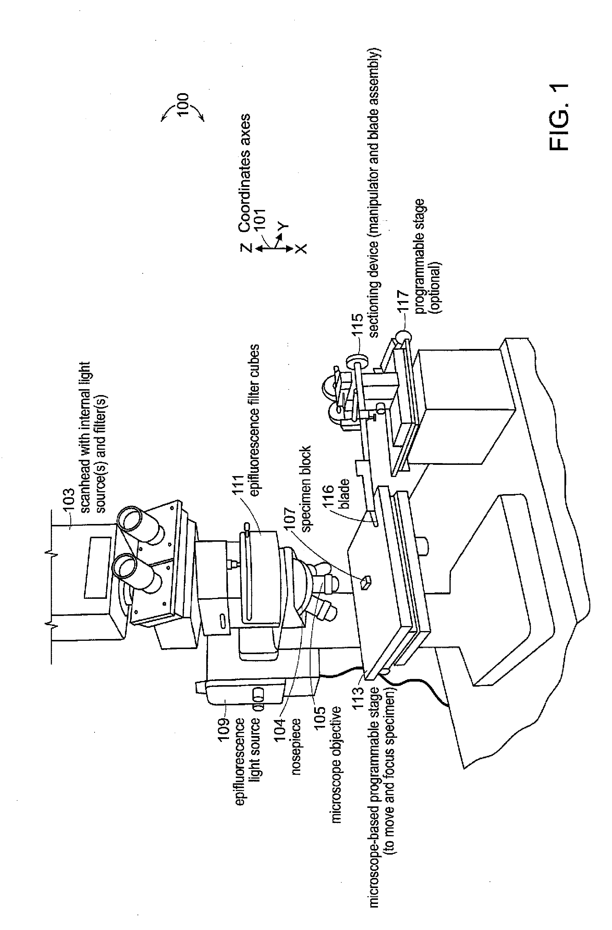
The present invention is a system and method for generating a three-dimensional image of a specimen using a microscope. The system includes an objective, optical elements, a sectioning device, a programmable stage, a programmable focus controller, a sensor, an image and sectioning tracker, an imaging controller, a reconstruction unit, an identification unit, a feature matching unit, an offset calculation unit, and a processing unit. The system can also include a display unit and a transmit unit to transmit the data to a reconstruction server or a storage unit. The sectioning device can oscillate a blade in a uni-dimensional manner. The technical effects of the invention include improved accuracy in imaging and sectioning, and the ability to generate a three-dimensional image of a specimen.

Problems solved by technology

However, microscopes can generally reveal structures only at or near the surface of specimens.
In so doing, precise spatial relationships between structures within the slices are altered making it difficult or impossible to describe these relationships within the intact specimen.
An advanced and expensive application of two-photon microscopy allows imaging up to 1 mm, but light scattering still limits the resolution at which structures may be viewed.

Method used


Image

  • System and methods for thick specimen imaging using a microscope based tissue sectioning device
  • System and methods for thick specimen imaging using a microscope based tissue sectioning device
  • System and methods for thick specimen imaging using a microscope based tissue sectioning device

Examples


Embodiment Construction

[0042]A description of example embodiments of the invention follows.

[0043]Investigations into the mechanisms underlying neural development, such as growth and differentiation, are enhanced by an ability to develop images of neural structure at a microscopic level. To label cells selectively, neuronal tracers can be injected at specific sites in the nervous system. In addition, transgenic mice are available that express fluorescent proteins in subsets of neurons. Techniques for imaging fluorescent structures in thick specimens include confocal and multi-photon microscopy; however, light scattering limits the depth at which signals can be acquired with high resolution. Electron microscopy and standard histology techniques overcome the limitations due to light scattering. Nevertheless, these techniques are not commonly used to reconstruct images of structures in thick specimens because of the difficulty of collecting, aligning, and segmenting serial sections. A need remains for improve...


PUM


Abstract

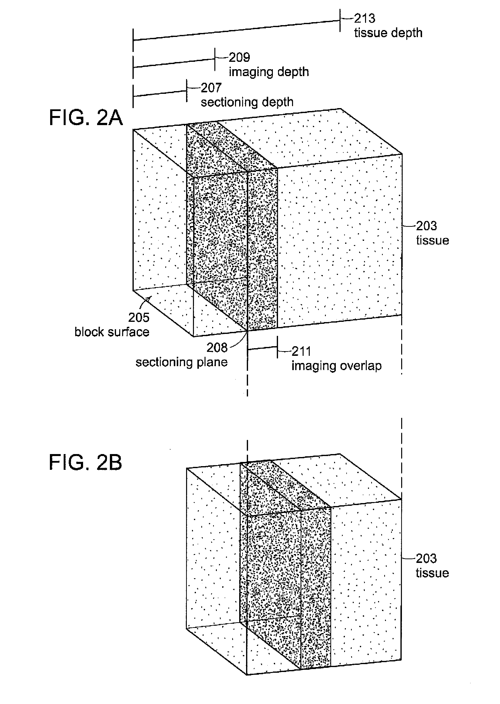
Systems and methods according to embodiments of the present invention facilitate imaging and sectioning of a thick specimen that allow for 3D image reconstruction. An example embodiment employs a laser scanning microscope and sectioning device, where the specimen, and optionally, the sectioning device are affixed to respective programmable stages. The stage normally used for aligning the specimen with the microscope objective is used as an integral component for sectioning the specimen. A specimen is imaged such that the imaging depth is less than the sectioning depth to produce overlap in contiguous sets of images; both acts are repeated until the imaging is completed. A substantially or completely seamless 3D image of the specimen is reconstructed by collecting sets of 2D images and aligning imaged features of structures in overlapping images or portions thereof. Specimen may be from a human, animal, or plant.

Description

INCORPORATION BY REFERENCE OF MATERIAL ON COMPACT DISK[0001]This application incorporates by reference three-dimensional (3D) images in the form of movies in .wmv format contained on compact disks filed concurrently herewith. Each compact disk is being filed in duplicate. The 3D images represent specimens upon which extended-depth confocal microscopy has been employed in accordance with an example embodiment of the present invention. The specimens are transgenic mouse tissue specimens imaged with high spatial resolutions and at significant depths and volumes.[0002]The following files are contained on the compact discs:[0003]a) File name: Occipital-Lobe-320×320×360 um-sections.wmv; created May 18, 2007, 3.60 MB in size. (3D reconstruction of 1×1×12 overlapping stacks, sectioning every 25 microns; blue=cfp, green=yfp, red=dsRed)[0004]b) File name: Frontal-Lobe-1.9×1.3×65 mmsectioning-80 um.wmv; created May 16, 2007, 4.34 MB in size. (3D reconstruction of 3×2×9 overlapping stacks, sect...

Claims


Application Information

Patent Timeline
Patent Type & Authority Applications(United States)
IPC IPC(8): G06T15/00G06K9/00
CPCG02B21/006G06T7/0028G01N2001/2873G06T2207/10064G06T2207/30004G06T2207/10056G06T7/33
Inventor TURNEY, STEPHEN G.SHEARD, PHILIP W.
Owner PRESIDENT & FELLOWS OF HARVARD COLLEGE
Learn More