Vapor deposition apparatus and method of vapor deposition making use thereof

a technology of vapor deposition apparatus and vapor deposition method, which is applied in the direction of chemical vapor deposition coating, ion implantation coating, coating, etc., can solve the problems of uneven phosphor or scintillator deposit, both measures in favor of homogeneity, and complicated steering and temperature control at the front and back sides of the suppor

Inactive Publication Date: 2009-04-16
T2PHARMA GMBH
View PDF2 Cites 20 Cited by
  • Summary
  • Abstract
  • Description
  • Claims
  • Application Information

AI Technical Summary

Benefits of technology

[0011]The above-mentioned advantageous effects are realized by making use of a particular vapor deposition apparatus comprising a container in form of a boat or crucible for the raw materials to become vaporized and to become deposited onto a substrate or support mounted in said vapor deposition apparatus, wherein said container is provided with an assembly of perforated covers or lids, in

Problems solved by technology

However both measures in favor of homogeneous deposit of the desired phosphor or scintillator material, more particularly with respect to the steering and the control of the temperature at the front as well as at the back side of the support, are rather complicated.
Anyhow in any evaporation process care should be taken in order to avoid “spot errors” or “pits”, resulting in uneven deposit of phosphors or scintillators, due to spitting of the liquefie

Method used


Image

  • Vapor deposition apparatus and method of vapor deposition making use thereof
  • Vapor deposition apparatus and method of vapor deposition making use thereof
  • Vapor deposition apparatus and method of vapor deposition making use thereof

Examples


examples

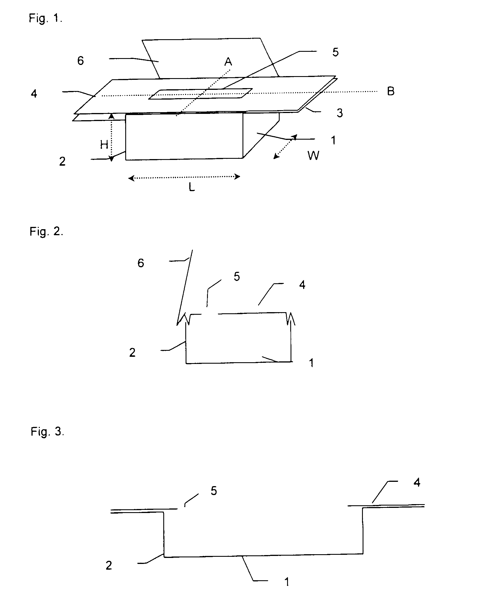
[0070]In a vapor deposition apparatus a rectangular boat or crucible (2) having as dimensions 15 cm in its length direction, 3.5 cm in its width direction and 4.75 cm in its height direction was fold from a refractory material plate of tantalum, delivered by H. C. Starck, Liaison Office Benelux, Mijdrecht, The Netherlands.

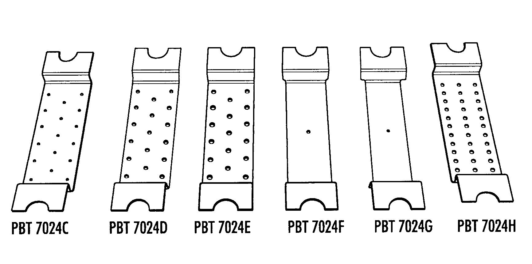
[0071]The crucible (1) thus folded, was provided with notches and perforations as set out in US-A 2006 / 0013966 in order to get the resistively heated crucible to be heated in a homogeneous way as presence of notches and perforations avoids cooling by the clamps, thanks to passage of equal amounts of energy in form of electrical power through a smaller crucible section, thereby reducing mass effects to a considerable extent.

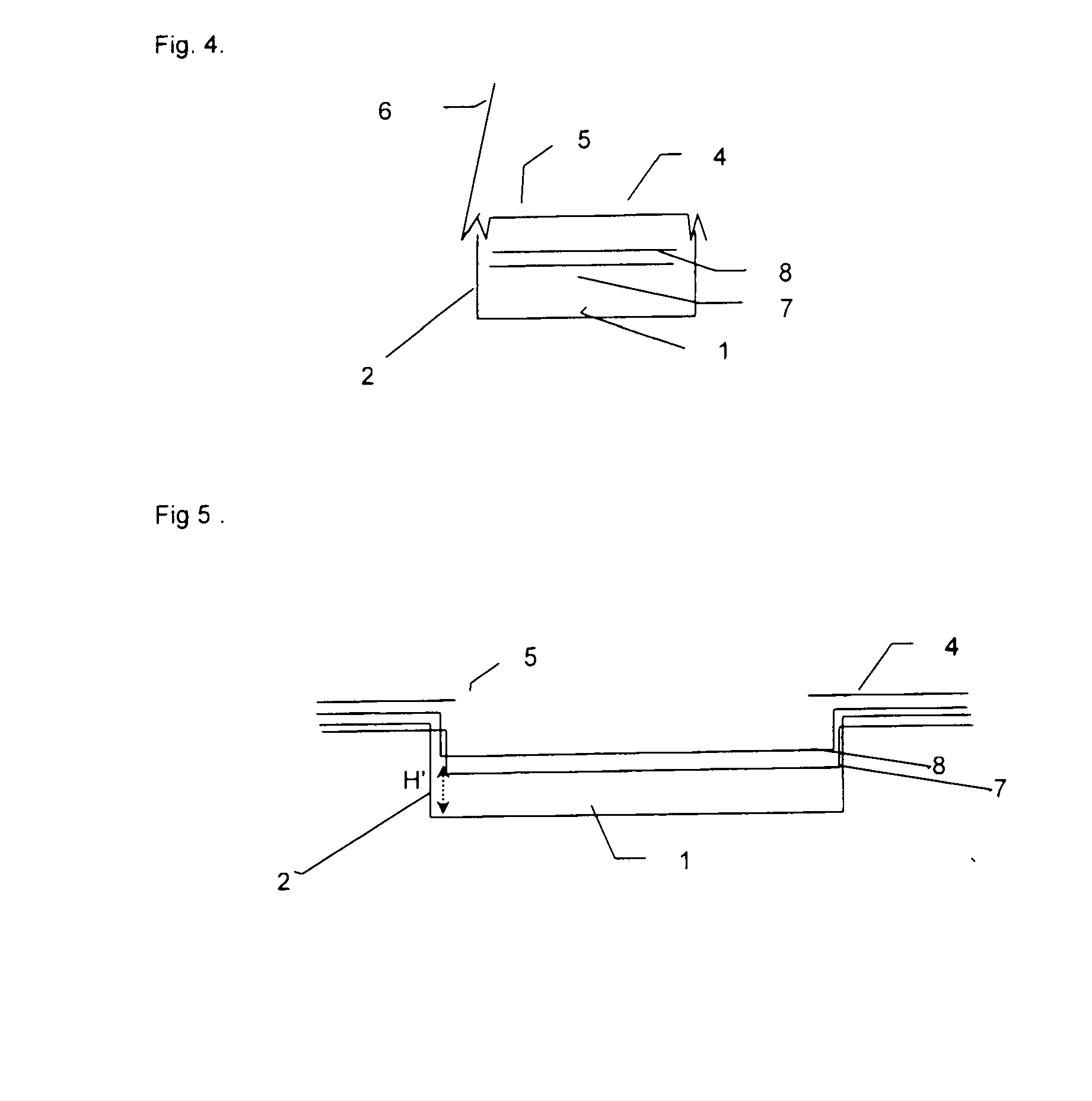
[0072]The first or outer lid was covering the crucible on top (position: 0), while the second or inner lid was more close to the bottom as positioned 15 mm under the first lid or cover.

[0073]In order to connect the crucible and the electrodes req...


PUM

PropertyMeasurementUnit
Fractionaaaaaaaaaa
Diameteraaaaaaaaaa
Diameteraaaaaaaaaa

Abstract

A vapor deposition apparatus comprises as a vaporization assembly a container in form of a boat or crucible and a support for vapor depositing phosphor or scintillator material thereupon from raw materials present in said container, wherein said boat or crucible internally comprises an assembly of two perforated covers or lids, one of which is an outer lid (also called first lid) more close to the said support and the other cover is an inner lid (also called second lid) more close to the bottom of the said crucible; and wherein perforations present in said outer lid represent a total surface exceeding the total surface of perforations present in said inner lid more close to the bottom of the said crucible and wherein in said vapor deposition apparatus the said raw materials or the bottom of the said crucible cannot be directly seen through said perforations from any point of said support; thereby providing the manufacturing of a radiation image storage phosphor layer on a support or substrate, by a vapor depositing step of raw materials of an alkali metal halide salt and a lanthanide dopant salt or a combination thereof in order to ensure vapor deposition of a binderless needle-shaped storage phosphor layer in the said vapor deposition apparatus, so that a ratio between the total surface of perforations in said inner lid more close to the bottom of crucible and the total surface of perforations in said outer lid more close to the support is not more than 1.0.

Description

FIELD OF THE INVENTION[0001]The present invention relates to a vapor deposition apparatus providing homogeneous deposition onto a substrate or support, mounted therein, of phosphor or scintillator materials from raw materials present in heated crucible(s), thereby, besides avoiding “spot errors” or “pits” resulting in uneven deposit due to spitting of liquefied raw materials, provoking a more constant deposition velocity onto said substrate, without influencing the substrate temperature.BACKGROUND OF THE INVENTION[0002]In physical vapor deposition (PVD) as well as in chemical vapor deposition (CVD) techniques, factors providing deposition of homogeneous phosphor or scintillator coating compositions and homogeneous layer thicknesses over the entire surface thereof, besides use of especially designed electrically heated crucible(s), are related with the distance determining the profile of the vapor cloud at the position of the substrate, as has e.g. been described in US-A 2004 / 0219289...

Claims


Application Information

Patent Timeline
IPC IPC(8): B05D5/06C23C16/00
CPCC23C14/243C23C14/0694
Inventor TAHON, JEAN-PIERRE
Owner T2PHARMA GMBH
Why Eureka
Try Eureka