Fuel cell system
- Summary
- Abstract
- Description
- Claims
- Application Information
AI Technical Summary
Benefits of technology
Problems solved by technology
Method used
Image

Examples
embodiment 1
[0128]In Embodiment 1 of the present invention, primary cooling water flowing through a primary cooling water supplying and discharging system is utilized as a medium for cooling (hereinafter simply referred to as a “cooling medium”), thereby forcibly cooling down in the condenser the off gas discharged from the polymer electrolyte fuel cell. Thus, the water available to humidify the fuel gas is forcibly increased.
[0129]First, the configuration of a fuel cell system according to Embodiment 1 of the present invention will be explained.
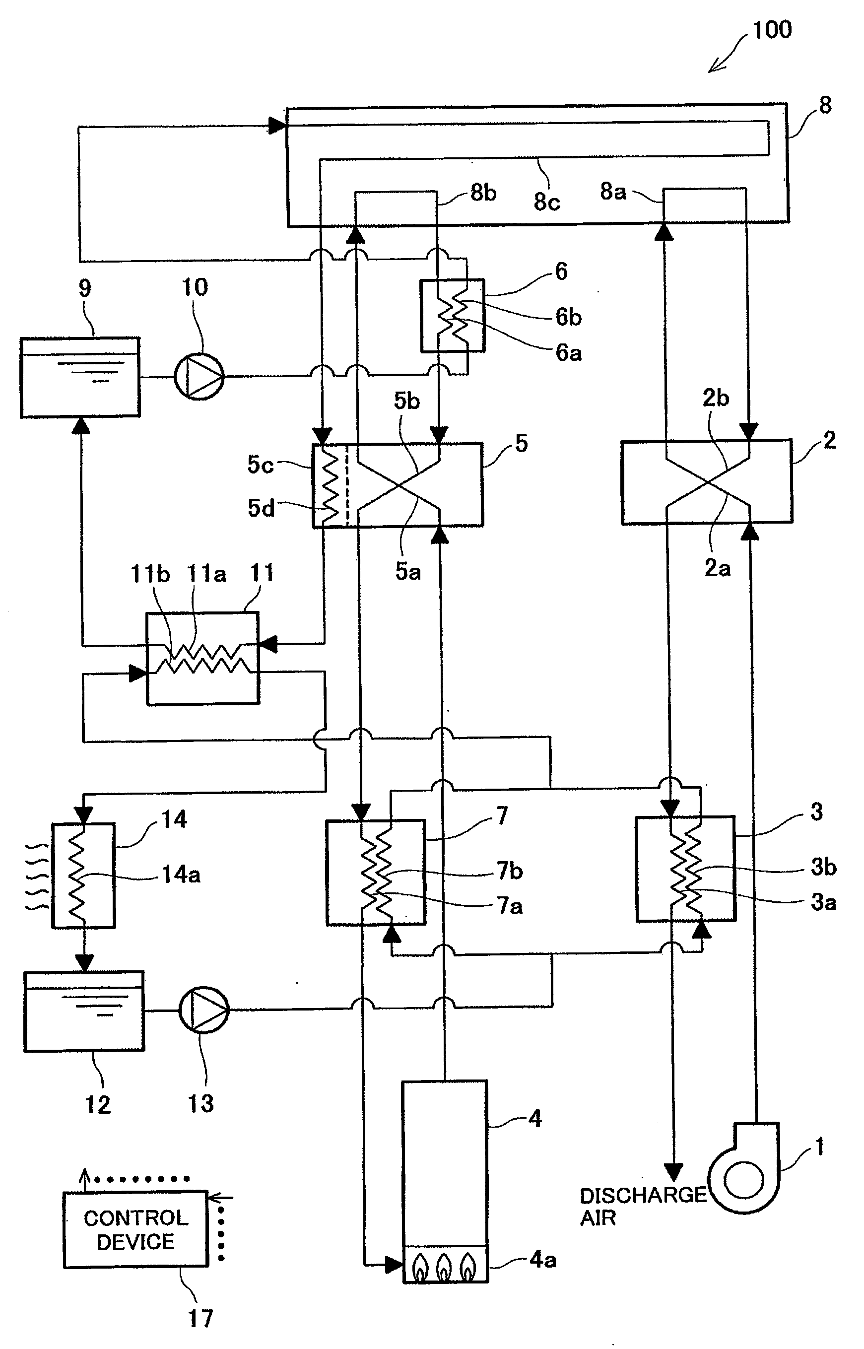
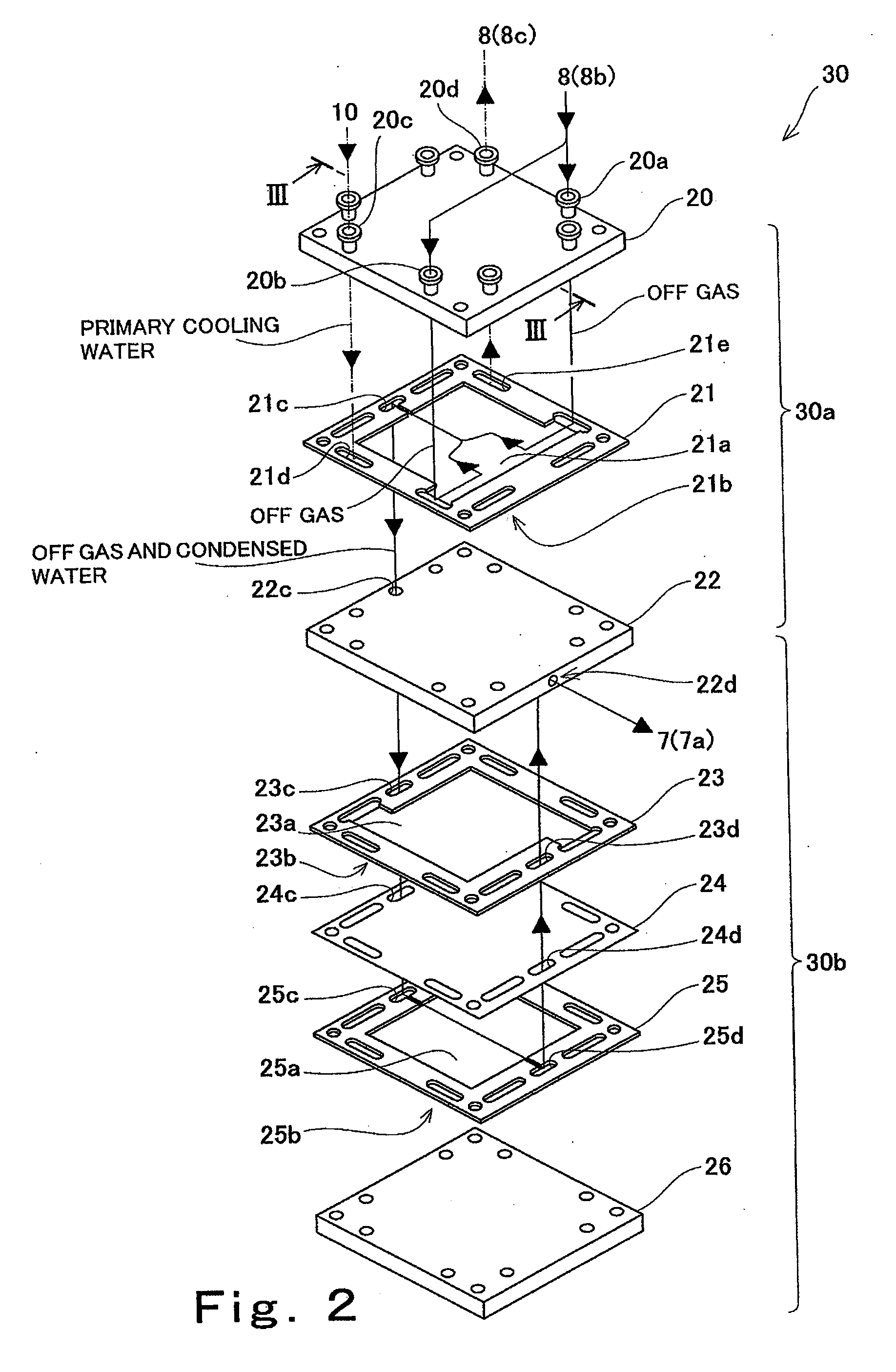
[0130]FIG. 1 is a block diagram schematically showing a part of the configuration of the fuel cell system according to Embodiment 1 of the present invention. In FIG. 1, each of solid lines having arrows denotes a connection state between components in the fuel cell system and a flow direction of the fuel gas, an oxidizing gas, the primary cooling water, or secondary cooling water in an electric power generating operation. In the following explanation, f...
example 1
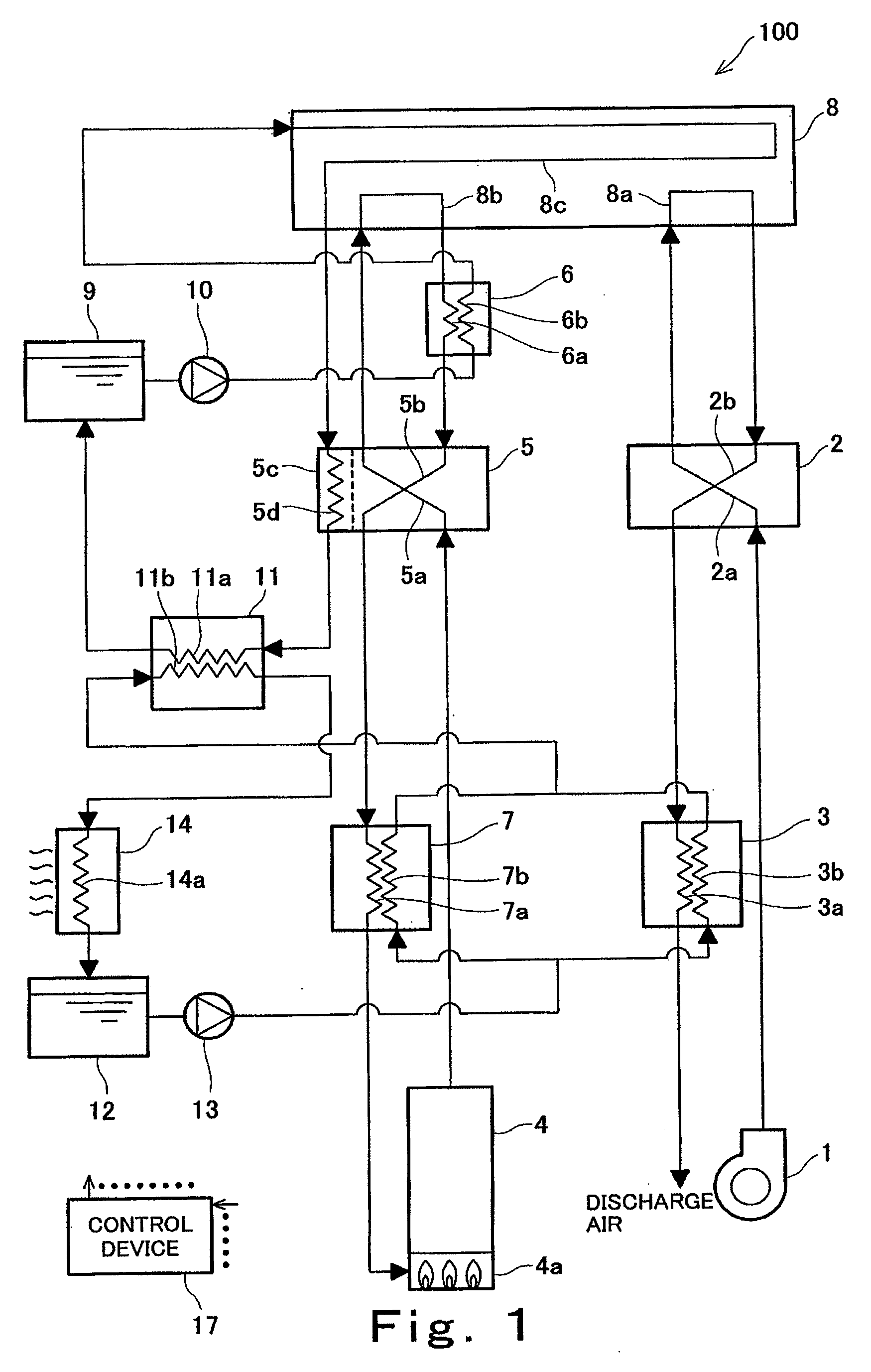
[0192]Effects obtained by the present invention were verified by using the fuel cell system including the block configuration shown in FIG. 1 and the condensing and humidifying device shown in FIGS. 2 and 3.
[0193]Used in the present verification was a stationary polymer electrolyte fuel cell whose rated output power was 1 kw. The number of stacked cells of the polymer electrolyte fuel cell was 20. An electrode surface area of the polymer electrolyte fuel cell was 200 cm2. When the fuel gas and the oxidizing gas were supplied to the polymer electrolyte fuel cell, the fuel utilization ratio (Uf) was 75%, the oxygen utilization ratio (Uo) was 50%, and a load whose load current was 80 A (current density was 0.4 A / cm2) was connected to the polymer electrolyte fuel cell, the output voltage of 14.5 V (average cell voltage of 0.725 V) and the output power of about 1.15 kw were obtained. At this time, the fuel gas was supplied to the fuel gas passage of the polymer electrolyte fuel cell such...
embodiment 2
[0205]In Embodiment 2 of the present invention, the secondary cooling water flowing through the secondary cooling water supplying and discharging system is utilized as the cooling medium to forcibly cool down in the condenser the off gas discharged from the polymer electrolyte fuel cell. Thus, the water available to humidify the fuel gas is forcibly increased.
[0206]FIG. 5 is a block diagram schematically showing a part of the configuration of the fuel cell system according to Embodiment 2 of the present invention. In FIG. 5, each of solid lines having arrows denotes a connection state between components in the fuel cell system and a flow direction of the fuel gas, the oxidizing gas, the primary cooling water, or the secondary cooling water in the electric power generating operation.
[0207]As shown in FIG. 5, a fuel cell system 200 according to Embodiment 2 of the present invention is different in configuration from the fuel cell system 100 according to Embodiment 1 only in that: the ...
PUM
 Abstract
Description
Claims
Application Information