Fourth harmonic generating system using optical double side-band suppressed carrier modulator

a carrier modulator and optical double sideband technology, applied in the field of fourth harmonic generating system using optical double sideband suppressed carrier modulator, can solve the problem of limited frequency difference between usb signal and lsb signal

Inactive Publication Date: 2009-04-23
NAT INST OF INFORMATION & COMM TECH
View PDF8 Cites 27 Cited by
  • Summary
  • Abstract
  • Description
  • Claims
  • Application Information

AI Technical Summary

Benefits of technology

[0012]The present invention is also based on the idea that by using a radio signal generator adopting the above-mentioned system, radio signals of frequencies (f0+2fm) and (f0−2fm) or a frequency (4fm) can be easily generated.

Problems solved by technology

However, since a frequency of a modulating signal is constrained by a modulation signal source of a system, frequency difference between an USB signal and an LSB signal is limited.

Method used


Image

  • Fourth harmonic generating system using optical double side-band suppressed carrier modulator
  • Fourth harmonic generating system using optical double side-band suppressed carrier modulator
  • Fourth harmonic generating system using optical double side-band suppressed carrier modulator

Examples


embodiment 1

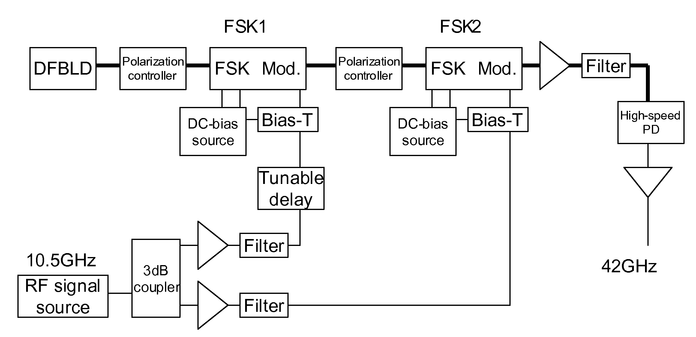
[0113]Hereinafter, the present invention is explained referring to an embodiment. FIG. 7 is a block diagram showing a system of the present embodiment. In FIG. 7, DFBLD represents a distributed-feedback laser diode, PC represents a polarization controller, FSK Mod. represents an optical frequency-shift keying modulator as a DSC-SC modulator, DC-bias source represents a source of DC bias voltage applied to an optical frequency-shit keying modulator, RF signal source represents a radio frequency signal source as a modulating signal source, Tunable delay represents a variable delay device for providing an arbitrary time difference between modulating signals of the two optical modulators, High-speed PD represents a high-speed optical detector, and triangles in the figure represent any amplifier. Modulating frequency of 10.5 GHz was used. Frequency of output signal from the high-speed optical detector was 42 GHz.

[0114]FIG. 8 is a spectrum diagram showing an output from the second modulat...

embodiment 2

Demonstration Experiment of the Principle of High Extinction Ratio (On / Off) by Using a FSK modulator

[0118]FIG. 11 is a schematic diagram showing an experimental system used in this experiment. In this example, an optical modulator as shown in FIG. 12 is used, and an RF signal and a DC signal are applied to an RFA electrode A and an RFB electrode B which are sub MZ waveguide electrodes. An intensity modulator with high extinction ratio is realized by adjusting an intensity balance between the arms of the main MZ by using the sub MZ of the FSK modulator. A DC bias was applied to the RFA electrode A the RFB electrode B, and the balance was adjusted. On-off switching was performed on the RFC electrode C.

[0119]The following elements are used in the experimental system. As an optical source, the combination of HP8166A and 81689A, respectively produced by Agilent Co., was used. The setting value was 1550 nm, and the observed value was 1549.925 nm. The setting value of intensity was 5.94 dB...

embodiment 3

1. DSB-SC Modulation Using High Extinction Ratio On-Off by FSK Modulator

[0127]An improvement of a carrier suppression ratio at a time of DSC-SC modulation was attempted by adjusting an intensity balance between the arms of the main MZ by using the sub MZ of FSK modulator, and realizing an intensity modulator with high extinction ratio. By doing this, it is shown that an optical FSK modulator can be used as a DSB-SC modulator.

2. Experimental System

[0128]In the experimental system of embodiment 3, the following elements were used. As an optical source, the combination of HP8166A and 81689A, respectively produced by Agilent Co., was used. The setting value was 1550 nm, and the observed value was 1549.925 nm. The setting value of intensity was 5.94 dBm, and the observed value was 2.68 dBm. An output light was inputted to the FSK modulator via a polarization controller. As a bias power source, three R6144s, produced by Advantest Co. were used. As an optical modulator, T.SBX1.5-10-AOC-P-F...


PUM

PropertyMeasurementUnit
frequencyaaaaaaaaaa
center frequencyaaaaaaaaaa

Abstract

The present invention is to provide an optical modulating system for generating a signal of a frequency (f0+2fm) and a signal of a frequency (f0−2fm) and suppressing a signal of a frequency (f0) by a DSB-SC modulator.
A fourth harmonic generating system for solving the above problem comprises a first DSB-SC modulator (2) a second DSB-SC modulator (3) and a signal control section (5) for controlling a modulating signal from a signal source (4) for generating modulating signals applied to the first and second DSB-SC modulators (2,3) so that a lower side-band signal (f0) generated by modulating the upper side-band signal of the DSB-SC modulator (2) by the DSB-SC modulator (3) and an upper side-band signal (f0) generated by modulating the lower side-band signal of the DSB-SC modulator (2) by the DSB-SC modulator (3) cancel each other.

Description

CROSS REFERENCE TO RELATED APPLICATION[0001]The present disclosure relates to subject matter contained in the international patent application No. PCT / JP2006 / 315657 filed on Aug. 8, 2006, and Japanese Patent Application No. 2005-229115 filed on Aug. 8, 2005, the disclosure of which is expressly incorporated herein by reference in its entirety.BACKGROUND OF THE INVENTION[0002]1. Field of the Invention[0003]The present invention relates to a fourth harmonic generating system using an optical double side-band suppressed carrier modulator and the like.[0004]2. Description of the Related Art[0005]As an optical modulator, an optical double side-band suppressed carrier modulator (DSB-SC modulator) is known. Specifically, FIG. 37 of Japanese Patent Application Laid-Open No. 2004-252386, for example, discloses a DSB-SC modulator having a Mach-Zehnder (referred to below as MZ) which has phase modulators on its both arms and a fixed phase shifter on one of its arms. A DSB-SC modulator, ideally...

Claims


Application Information

Patent Timeline
Patent Type & Authority Applications(United States)
IPC IPC(8): H04B10/10G02F1/35H04B10/2507H04B10/516H04B10/548H04B10/61H04L27/20
CPCG02F1/2255H04L27/04H04B2210/006H04B10/506
Inventor KAWANISHI, TETSUYAIZUTSU, MASAYUKISAKAMOTO, TAKAHIDETSUCHIYA, MASAHIRO
Owner NAT INST OF INFORMATION & COMM TECH
Why Eureka
Try Eureka