Exhaust sound and emission control systems

a technology of exhaust sound and emission control, applied in the direction of engines, machines/engines, mechanical equipment, etc., can solve the problems of aluminized coating burning off, generally not being combined into a single unit, adversely affecting the environment, etc., and achieve the effect of enhancing emissions reduction and reducing exhaust components

Inactive Publication Date: 2009-04-30
MAROCCO GREGORY M
View PDF69 Cites 2 Cited by
  • Summary
  • Abstract
  • Description
  • Claims
  • Application Information

AI Technical Summary

Benefits of technology

[0013]The exhaust sound and emission control systems of the present invention comprise a series of devices for attenuating sound and noxious emissions primarily for, but not limited to, an automobile exhaust system. In one aspect, the system relates to a catalytic converter and resonator combination, combined within a single canister or shell. The combination device may be installed between the engine and a muffler at or near the downstream or exhaust outlet end of the exhaust system, with the system perhaps including an additional catalytic converter(s) upstream of the catalytic converter and resonator combination. The placement of the catalytic converter and resonator combination forward of the muffler and tailpipe of the exhaust system, with the converter element forward of the resonator element, ensures that the converter portion of the combination will receive exhaust gases at a sufficiently high temperature to produce the desired catalytic reaction and thereby oxidize and / or reduce the exhaust components to harmless products. The catalytic converter element may be formed of a thin wall ceramic material, for further efficiency. Heated and / or electronic catalytic converter devices may be implemented to enhance emissions reduction.

Problems solved by technology

By the time of the 1950s, it was becoming apparent that the ever-increasing volume of automobile and truck traffic was generating exhaust emissions, which were adversely affecting the environment.
However, long before the recognition of chemical or particulate automobile exhaust emissions as a hazard, another type of automobile exhaust emission had been recognized, i.e., noise or sound.
These two types of emissions control devices, i.e., catalytic converters and mufflers or other sound attenuating devices, have generally not been combined into a single unit due to conflicting characteristics and physical requirements.
Very high temperatures cause the aluminized coating to be burned off, and cause both the interior and (after removal of any coating) exterior to be oxidized, to the point of burn-through or rust-through, in relatively short order.
While mufflers and other related devices have been constructed of stainless steel in order to reduce oxidation problems, these devices are relatively costly due to the material used and the difficulty in working with such material, in comparison to mild steel.
On the other hand, catalytic converters require relatively high temperatures for efficient operation.
Thus, most catalytic converters are constructed of relatively costly materials in order to withstand the heat generated therein.
However, heretofore no combining of a catalytic converter and a resonator has been accomplished, to the knowledge of the present inventor.

Method used


Image

  • Exhaust sound and emission control systems
  • Exhaust sound and emission control systems
  • Exhaust sound and emission control systems

Examples


embodiment 110

[0062]FIGS. 3 and 4 respectively provide an exploded perspective view and a side elevation view in section of another embodiment 110 of the present exhaust sound and emission control system invention. Like components between the system 10 of FIGS. 1 and 2 and the embodiment 110 of FIGS. 3 and 4 are indicated with identical reference numerals, with only those components that are different between the two embodiments being indicated by different reference numerals.

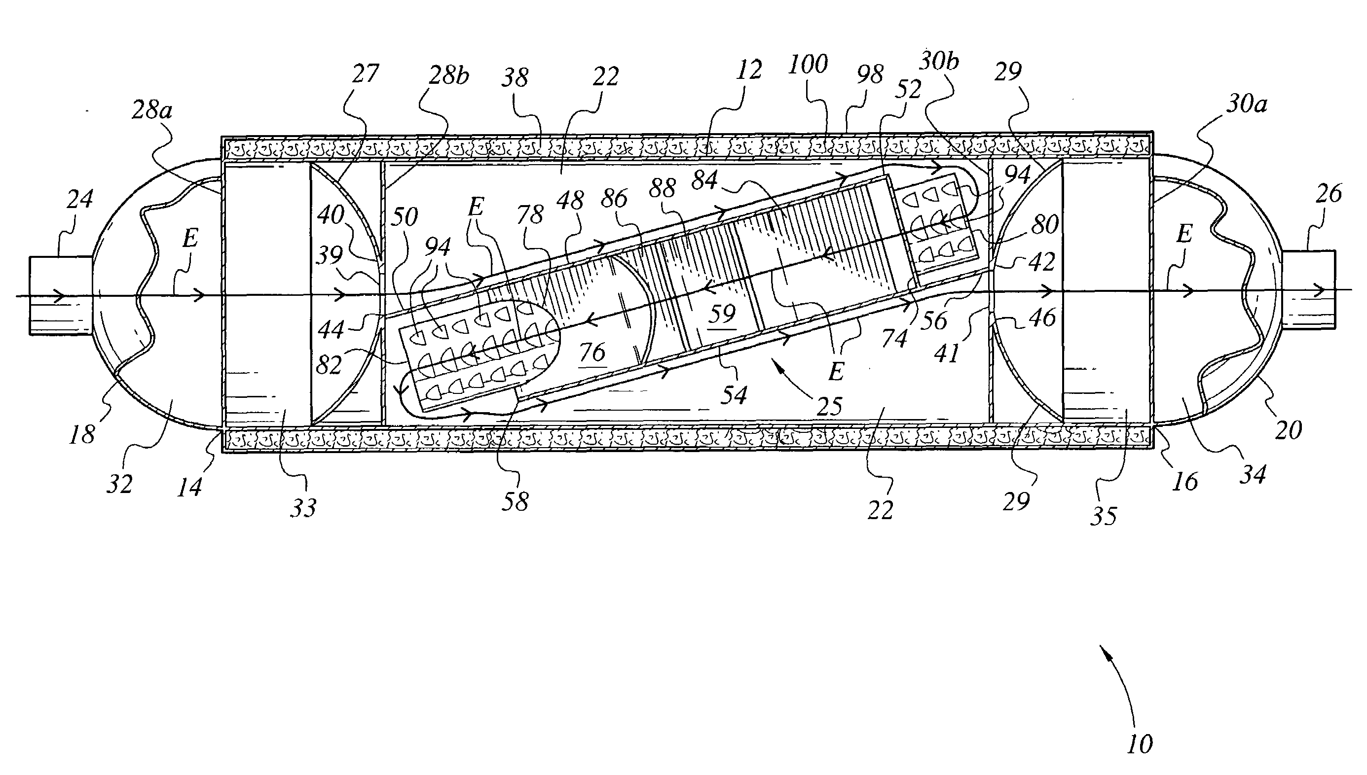
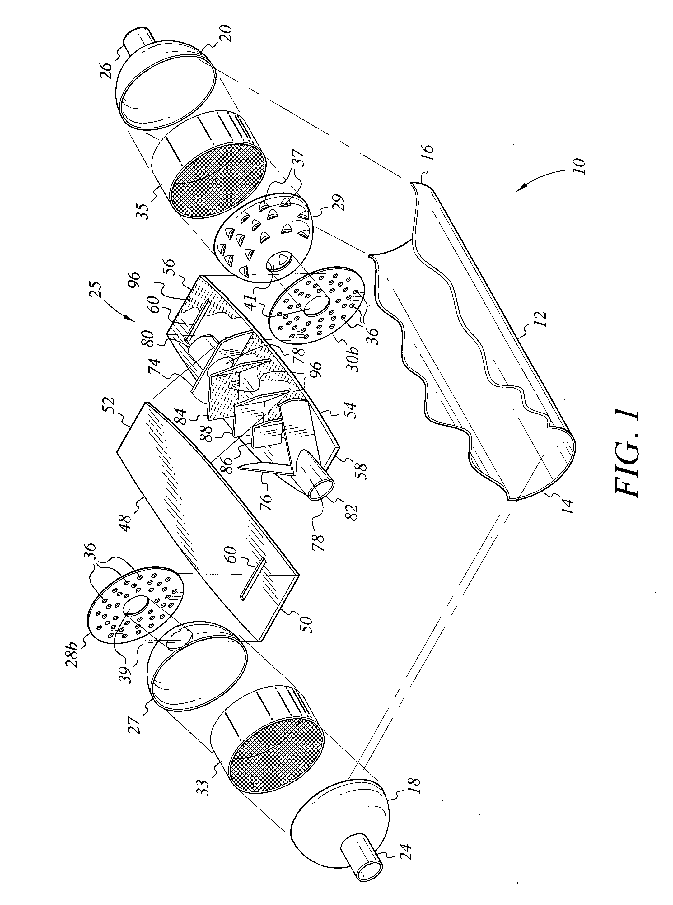
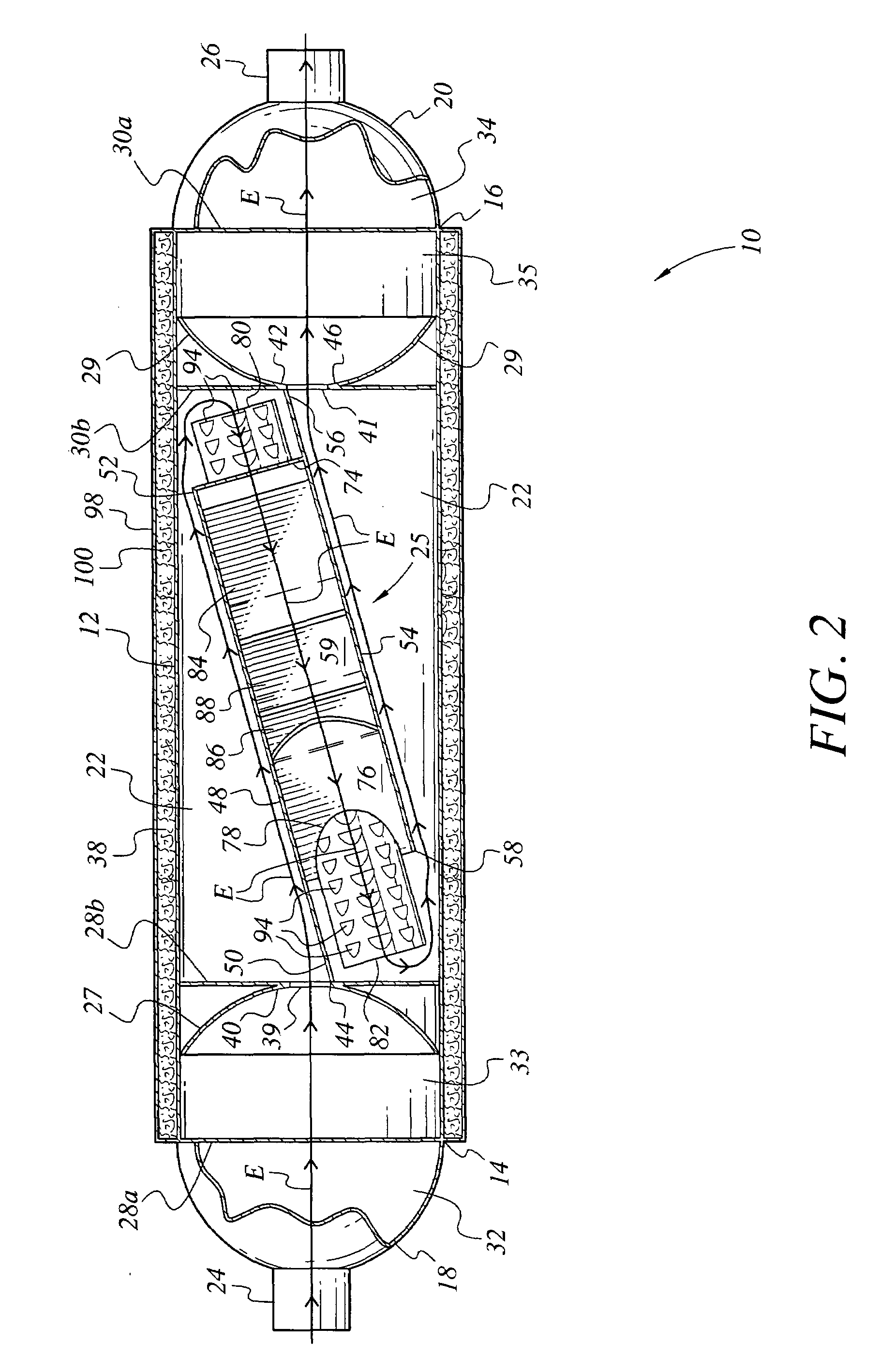
[0063]The exhaust emission and control system device 110 of FIGS. 3 and 4 comprises a generally cylindrical unit. The internal components of the exhaust system 110 are enclosed in an elongate external housing or shell 12 (shown with one side broken away in FIG. 3, for clarity in the drawing Fig.) having an inlet end 14 and opposite outlet end 16. Each end 14 and 16 of the housing 12 has an external end plate sealed thereto, respectively inlet end plate 18 and outlet end plate 20. These external end plates 18 and 20 may compr...

embodiment 10

[0080]It will be seen that the present exhaust sound and emission control system 110 may also incorporate such catalytic converter elements, e.g., elements 33 and 35, as shown in the embodiment 10 of FIGS. 1 and 2 and described further above. In addition, the present system 110 may also incorporate internal coatings 96 of emission reduction material therein if so desired, as shown in FIG. 3, e.g., platinum, rhodium, palladium, etc.

[0081]The relatively free flow characteristics of the present exhaust system result in a relatively small percentage of the exhaust gases actually contacting the internal surfaces of the device 110 (with the exception of the catalytic converter elements 33 and 35, if incorporated therewith). However, coating the internal surfaces with a catalytic conversion coating 96 as shown in FIG. 3, e.g., the internal surface of the housing 12, the separator panels 48 and 54, the entry, exit, and intermediate baffles or vanes 84 through 88, etc., nevertheless does pro...

embodiment 210

[0085]Moreover, an upstream and a downstream divider vane, respectively 212 and 214, are installed through the respective entry and exit pipes or tubes 80 and 82 in the embodiment 210 of FIGS. 5 and 6. These divider vanes 212 and 214 have lengths approximately equal to their respective tubes 80 and 82, and serve to smooth and separate the exhaust gas flow relative to the two sides of the series of chevron shaped baffles or guides 76, 86, and 88. Accordingly, the upstream divider vane 212 may extend between the two sides of the separate guide components 84a and 84b to the secondary intermediate baffle or guide 88, to preclude turbulent flow due to gases passing from one side of the assembly to the other.

[0086]FIGS. 7 through 9 respectively provide an exploded perspective view, a side elevation view in section, and a lateral view in section through line 9-9 of FIG. 8, of yet another embodiment 310 of the present exhaust sound and emission control system invention. Like components betw...


PUM


Abstract

The exhaust sound and emission control systems reduce sound and noxious emissions from an automotive exhaust. The system may have an exhaust resonator having one or more catalytic converter elements in combination therewith in a single device. Alternatively, the system may have multiple angularly disposed chambers therein, with a series of swept baffles or guides in one of the chambers, thereby combining resonator and muffler functions in a single device. In another alternative, the system has a series of longitudinal tubes therein in combination with a series of V-shaped guides or vanes, combining catalytic converter, muffler, and resonator functions in a single device. The various elements of the system, e.g., catalytic converter element(s), double wall shell, perforated tubes and multiple flow paths, interconnecting crossover tubes, etc., may be combined with one another as practicable.

Description

REFERENCE TO RELATED PATENT APPLICATIONS[0001]This application is a continuation-in-part of U.S. patent application Ser. No. ______ (presently unassigned) filed on Oct. 15, 2007, which is a continuation-in-part of U.S. patent application Ser. No. 11 / 198,484 filed on Aug. 8, 2005, now issued as U.S. Pat. No. 7,281,606 on Oct. 16, 2007, which is a continuation-in-part of U.S. patent application Ser. No. 10 / 663,751, filed on Sep. 17, 2003, now issued as U.S. Pat. No. 6,935,461 on Aug. 30, 2005, which is a continuation-in-part of U.S. patent application Ser. No. 09 / 135,804 filed on Aug. 18, 1998, now abandoned, and U.S. patent application Ser. No. 10 / 252,506 filed on Sep. 24, 2002, now issued as U.S. Pat. No. 6,651,773 on Nov. 25, 2003.BACKGROUND OF THE INVENTION[0002]1. Field of the Invention[0003]The present invention relates generally to automobile exhaust sound and emission control, including a catalytic exhaust converter and resonator installed within the exhaust system for the red...

Claims


Application Information

Patent Timeline
Patent Type & Authority Applications(United States)
IPC IPC(8): F01N1/08
CPCF01N1/08F01N2230/04F01N13/141F01N3/2885
Inventor MAROCCO, GREGORY M.
Owner MAROCCO GREGORY M
Why Eureka
Try Eureka