
Optical detection method and optical detection apparatus for a fine particle

a detection method and optical detection technology, applied in optical radiation measurement, fluorescence/phosphorescence, nuclear engineering, etc., can solve the problems of reducing the accuracy of the fluorescent light correction described above and the data analysis carried out based on the result of the fluorescent correction, affecting the accuracy of the analysis itself of the fluorescent light output signal, and affecting the accuracy of the fluorescent light correction. , to achieve the effect of reducing the damage to and deterioration of the fine particle by the laser beam,

Inactive Publication Date: 2009-04-30
SONY CORP
View PDF22 Cites 26 Cited by
  • Summary
  • Abstract
  • Description
  • Claims
  • Application Information

AI Technical Summary

Benefits of technology

[0014]Therefore, in the related art, where fluorescent light or scattered light having a high luminance level is detected, the intensity of the laser beam used as excitation light and the sensitivity of the photo-detector such as a PMT (Photo-Multiplier Tube) are set to values with which no saturation of the signal level occurs. This improves the accuracy in analysis of fluorescent light or scattered light having a high luminance level. However, since the level of an output waveform of a signal from fluorescent light or scattered light of a low luminance level further decreases, the analysis itself of the fluorescent light output signal may become difficult.
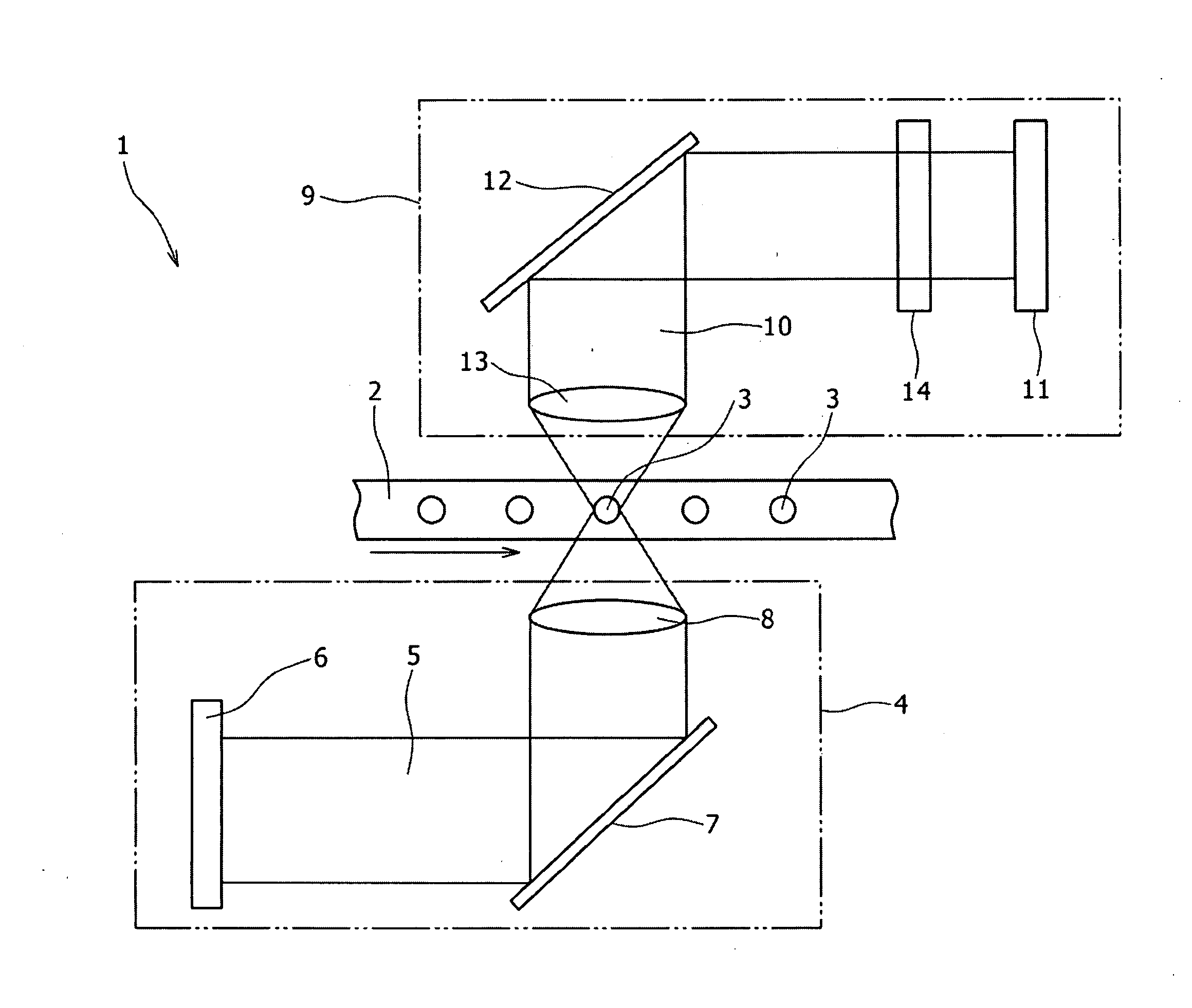
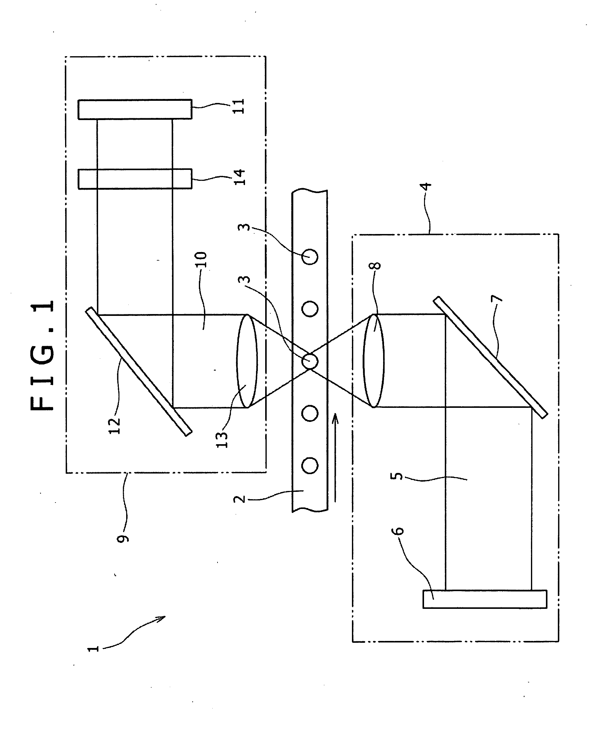
[0034]With the optical detection method and the optical detection apparatus, since the laser beam is formed as a pulse laser beam, damage to and deterioration of the fine particle by the laser beam can be reduced. Further, since the laser beam is irradiated while the pulse intensity thereof is modulated, a plurality of detection signals having different output levels from each other for individual wavelengths are obtained. Therefore, detection of high accuracy and superior reliability can be implement even where a plurality of fluorescent lights or scattered lights which exhibit a great difference in luminance level thereamong are to be detected.

Problems solved by technology

However, the detection methods and detection apparatus in related art described above have the following problems.
In particular, the first problem of the related-art detection methods resides in that, if a dispersion occurs with the intensity of fluorescent light or scattered light generated from fine particles, then the accuracy in fluorescent light-correction described above and data analysis which is carried out based on a result of the fluorescent correction degrades.
This problem is remarkable particularly where only one control voltage can be set for a plurality of anodes or photo-detectors.
However, since the level of an output waveform of a signal from fluorescent light or scattered light of a low luminance level further decreases, the analysis itself of the fluorescent light output signal may become difficult.
The second problem of the related-art detection methods resides in that laser beam irradiation sometimes damages fine particles or degenerates fine particles due to a temperature rise.
Further, the third problem of the related-art detection methods is that, when the temperature is high, a fluorescent dye qualifying fine particles is left off the surface of the fine particles and, when the light intensity is high, the fine particles are faded.
The problems are liable to occur particularly where two or more laser beans are irradiated and where the fine particle of an object of detection is a cell.

Method used


Image

  • Optical detection method and optical detection apparatus for a fine particle
  • Optical detection method and optical detection apparatus for a fine particle
  • Optical detection method and optical detection apparatus for a fine particle

Examples


second embodiment

[0068]Now, a method of optically detecting a fine particle qualified with two or more different fluorescent dyes as the present invention is described. For example, where a fine particle is qualified with two or more fluorescent dyes having excitation wavelengths different from each other, it is necessary to irradiate two or more laser beams having different wavelengths from each other upon the fine particle. Therefore, in the present embodiment, two or more pulse lasers having wavelengths λ different from each other are irradiated from the light irradiation section 4 of the optical detection apparatus 1 upon a fine particle with phases thereof displaced from each other while the pulse intensity is modulated.

[0069]FIG. 6 shows a graph wherein the axis of abscissa is the time and the axis of ordinate is the intensity and illustrates an example of an irradiation pattern of laser beams according to the optical detection method of the present embodiment. Referring to FIG. 6, in the dete...

first embodiment

[0080]It is to be noted that the configuration and the effect of the other part than that described above of the optical detection method of the present embodiment are similar to those of the detection method of the first embodiment described hereinabove.

[0081]Now, an optical detection method according to a third embodiment of the present invention is described. The detection method of the present embodiment is similar to the detection methods of the first and second embodiments described hereinabove except that an ultrashort pulse laser beam of a comb shape (hereinafter referred to as comb-like pulse) is used for laser beams to be irradiated from the light irradiation section.

[0082]FIGS. 9A and 9B show irradiation patterns when a comb-like pulse laser beam s irradiated upon a cell A and another cell B which have different damage intensities, respectively. Meanwhile, FIGS. 10A and 10B show irradiation patterns when a comb-like pulse laser beam is irradiated upon fine particles quali...


PUM


Abstract

Disclosed herein is an optical detection method and optical detection apparatus, the apparatus including: a light irradiation section configured to irradiate a laser beam upon one of fine particles which are successively fed in a flow path; and a light detection section configured to detect fluorescent light and / or scattered light generated from any of the fine particles upon which the laser beam is irradiated; the method including the steps of: irradiating a laser beam upon one of fine particles which are successively fed in a flow path; and detecting fluorescent light and / or scattered light generated from the fine particle; wherein the laser beam being formed as a pulse laser beam whose pulse intensity is modulated such that one laser beam or two or more laser beams having different wavelengths are irradiated by a plural number of times upon one fine particle with the intensity varied.

Description

CROSS REFERENCES TO RELATED APPLICATIONS[0001]The present invention contains subject matter related to Japanese Patent Application JP 2007-278907 filed in the Japan Patent Office on Oct. 26, 2007, the entire contents of which being incorporated herein by reference.BACKGROUND OF THE INVENTION[0002]1. Field of the Invention[0003]This invention relates to an optical detection method and an optical detection apparatus for individually identifying fine particles such as cells or micro beads. More specifically, the present invention relates to an optical detection method and an optical detection apparatus wherein the type of a fine particle is identified from fluorescent light or scattered light generated from the fine particle when a laser beam of a particular wavelength is irradiated upon the fine particle.[0004]2. Description of the Related Art[0005]Generally, where it is intended to identify a living body-related small particle such as a cell, a microorganism or a ribosome, an optical...

Claims


Application Information

Patent Timeline
Patent Type & Authority Applications(United States)
IPC IPC(8): A61N5/067G01J1/58
CPCG01N15/1425G01N15/1434G01N15/1459G01N2015/1006G01N2015/1438G01N21/64G01N21/00G01N21/39G01N21/62
Inventor SHINODA, MASATAKAIMANISHI, SHINGO
Owner SONY CORP
Learn More