
Minimally invasive spine internal fixation system

a spine and minimally invasive technology, applied in the field of bone implant systems and methods, can solve the problems of limited radiation exposure for patients and surgeons

Inactive Publication Date: 2009-04-30
BARRY RICHARD J
View PDF13 Cites 12 Cited by
  • Summary
  • Abstract
  • Description
  • Claims
  • Application Information

AI Technical Summary

Benefits of technology

[0021]The system and methods disclosed herein provide a high percentage, predictable spinal fusion using a safe, minimally invasive method to mechanically lock the motion segment in order to allow bone formation and fusion across the intervertebral joints with minimal tissue disruption. Vertebral fusion is achieved via instrumentation implanted through a 1 centimeter diameter portal.
[0070]Another aspect is a method of minimally invasively stabilizing first and second vertebrae in a patient comprising forming a first bone path into the vertebral body of the first vertebrae, forming a second bone path into the vertebral body of the second vertebrae, installing a first bone anchor in the first bone path, and installing a second bone anchor in the second bone path, wherein the first and second bone anchors comprise a distal portion configured to mate with the bone paths and proximal portion comprising a mounting surface. An interconnecting link is positioned over the first and second bone anchors to span first and second bone anchors, mating a first platform of the link with the mounting surface of the first bone anchor, and a second platform of the link with the mounting surface of the second bone anchor; and securing the link to compress the link on to the first and second bone anchors, thereby restraining motion of the first vertebrae with respect to the second vertebrae.

Problems solved by technology

Radiation exposure for the patient and surgeon are limited by the use of fluoroscopy to confirm, rather than guide, accurate placement of the bone anchors.

Method used


Image

  • Minimally invasive spine internal fixation system
  • Minimally invasive spine internal fixation system
  • Minimally invasive spine internal fixation system

Examples


Embodiment Construction

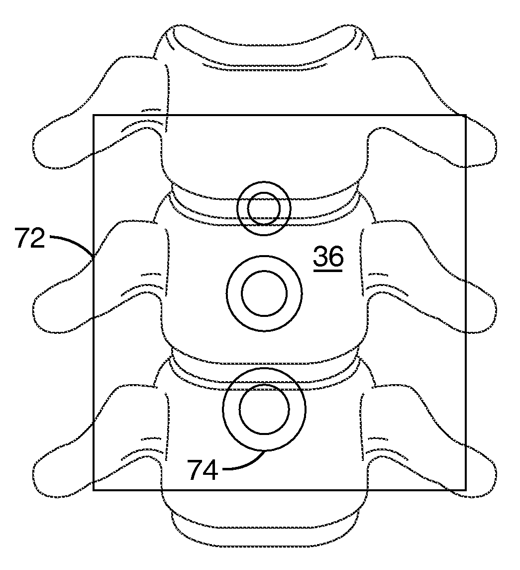
[0106]Referring more specifically to the drawings, for illustrative purposes the present invention is embodied in the systems and methods generally shown in FIG. 4 through FIG. 33. It will be appreciated that the systems may vary as to configuration and as to details of the parts, and that the method may vary as to the specific steps and sequence, without departing from the basic concepts as disclosed herein.

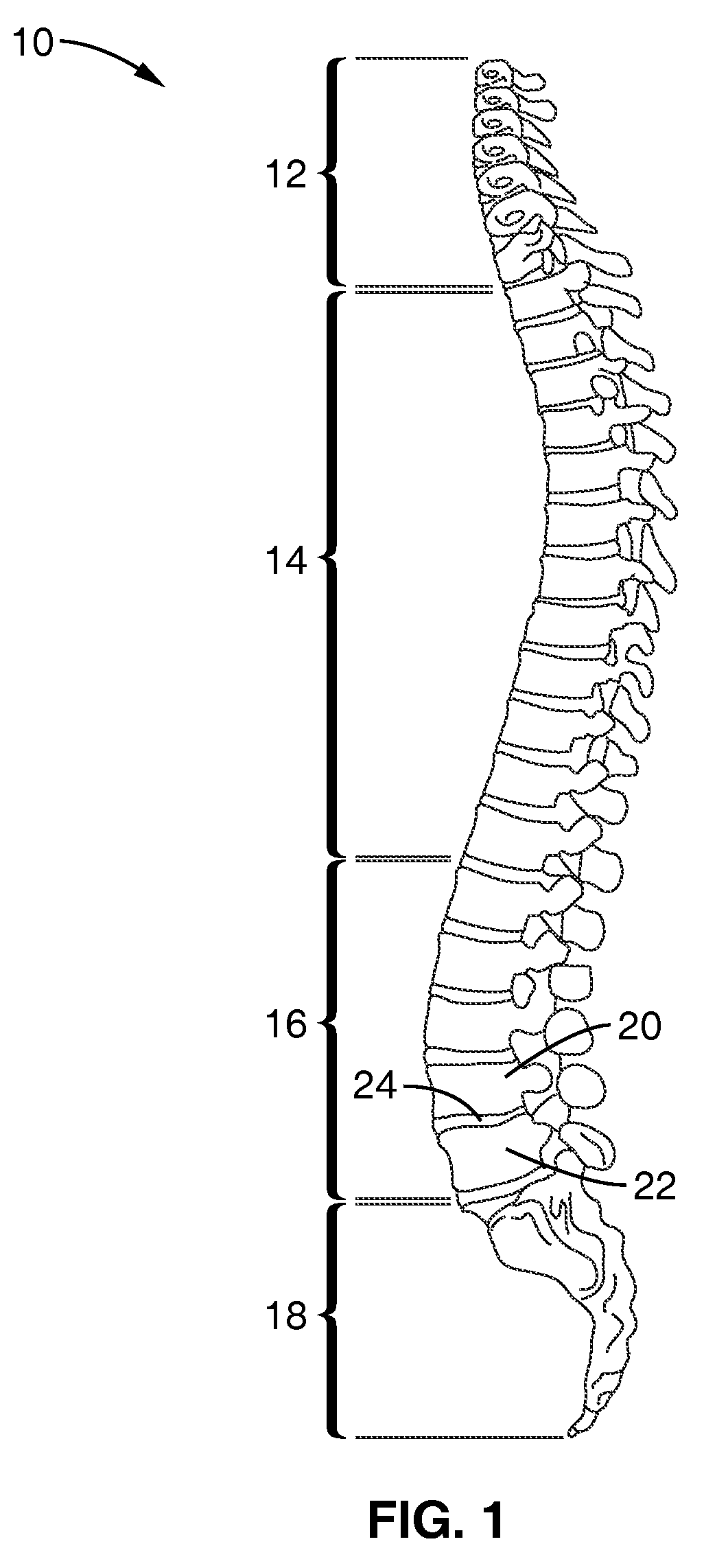
[0107]Referring to FIG. 1, a lateral view of the human spine 10 is illustrated showing the various regions of vertebrae: cervical 12, thoracic 14, and cervical 16. The basic biomechanical unit of the spine, referred to as a motion segment, consists of two adjacent vertebrae 20, 22 and the three joint articular complex through which they move and are constrained in relation to one another.

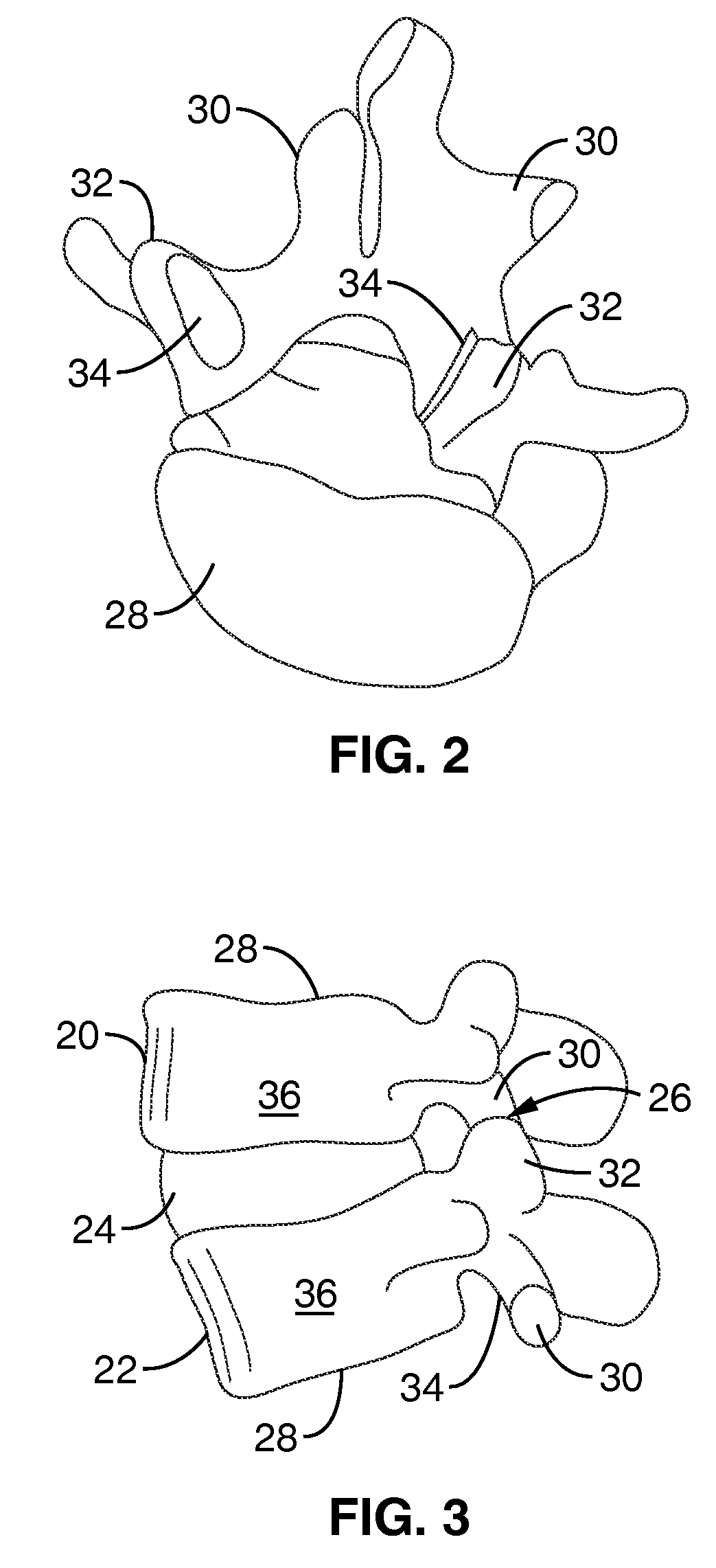
[0108]Referring to FIGS. 2 and 3, the cervical spine articulations consist of an intervertebral disc 24 located between the bodies 28 of the adjacent vertebrae 20, 22. Each vertebral body 28 is ...


PUM

PropertyMeasurementUnit
diameteraaaaaaaaaa
lengthaaaaaaaaaa
diameteraaaaaaaaaa

Abstract

A minimally invasive modular system is disclosed for stabilizing the anterior column of the spine through an anterior or lateral approach. Bone anchors are implanted into the vertebral bodies of adjacent vertebrae and serve as a foundation for a fixation system. The anchors comprise an interface surface that allows an interconnecting link to be secured to the anchors in a low-profile manner with minimum protrusion beyond the vertebral members. The link may be secured to the bone anchors to affect a compressive interlocking force between the bone anchors and vertebrae.

Description

CROSS-REFERENCE TO RELATED APPLICATIONS[0001]Not ApplicableSTATEMENT REGARDING FEDERALLY SPONSORED RESEARCH OR DEVELOPMENT[0002]Not ApplicableINCORPORATION-BY-REFERENCE OF MATERIAL SUBMITTED ON A COMPACT DISC[0003]Not ApplicableNOTICE OF MATERIAL SUBJECT TO COPYRIGHT PROTECTION[0004]A portion of the material in this patent document is subject to copyright protection under the copyright laws of the United States and of other countries. The owner of the copyright rights has no objection to the facsimile reproduction by anyone of the patent document or the patent disclosure, as it appears in the United States Patent and Trademark Office publicly available file or records, but otherwise reserves all copyright rights whatsoever. The copyright owner does not hereby waive any of its rights to have this patent document maintained in secrecy, including without limitation its rights pursuant to 37 C.F.R. §1.14.BACKGROUND OF THE INVENTION[0005]1. Field of the Invention[0006]This invention pert...

Claims


Application Information

Patent Timeline
Patent Type & Authority Applications(United States)
IPC IPC(8): A61B17/70A61B17/56A61B17/04A61B19/00A61B17/58
CPCA61B17/025A61F2310/00796A61B17/1671A61B17/68A61B17/701A61B17/7011A61B17/7091A61B17/92A61B2017/00915A61B2017/0256A61B2017/320044A61B2017/922A61B2019/461A61F2310/00407A61F2310/00461A61F2310/00544A61B17/1615A61B2090/061
Inventor BARRY, RICHARD J.
Owner BARRY RICHARD J
Learn More