Method for imaging surface roughness using acoustic emissions induced by ultrasound

a technology of ultrasound and surface roughness, applied in the field of ultrasonic non-destructive techniques for imaging surface roughness, can solve the problems of not producing high-resolution images at audio frequencies, unable to image surface roughness of anisotropic materials and thick layered structures, and requiring very complex signal processing methods to produce images, etc., to achieve high spatial resolution

Active Publication Date: 2009-05-07
MAYO FOUND FOR MEDICAL EDUCATION & RES
View PDF11 Cites 20 Cited by
  • Summary
  • Abstract
  • Description
  • Claims
  • Application Information

AI Technical Summary

Benefits of technology

[0014]The present invention overcomes the drawbacks of the previous methods for ultrasonic nondestructive testing (NDT) by providing a method that produces images with high spatial resolution while using acoustic energy at lower frequencies. More specifically, the present invention employs vibroacoustography (“VA”) for detecting micron-sized surface variations.

Problems solved by technology

First, they are unable to image surface roughness of anisotropic materials and thick layered structures.
Furthermore, they do not produce high resolution images at audio frequencies, and they require very complex signal processing methods to produce an image.
While the SAM method provides higher spatial resolution than the C-scan method, it presents a problem of heating, and thus possibly damaging, the object resultant from the high frequency focused ultrasound employed in SAM techniques.
Furthermore, the higher frequency ultrasound waves are more likely to be absorbed and attenuated by the object being tested, thus decreasing the efficiency of the imaging process.

Method used


Image

  • Method for imaging surface roughness using acoustic emissions induced by ultrasound
  • Method for imaging surface roughness using acoustic emissions induced by ultrasound
  • Method for imaging surface roughness using acoustic emissions induced by ultrasound

Examples


Embodiment Construction

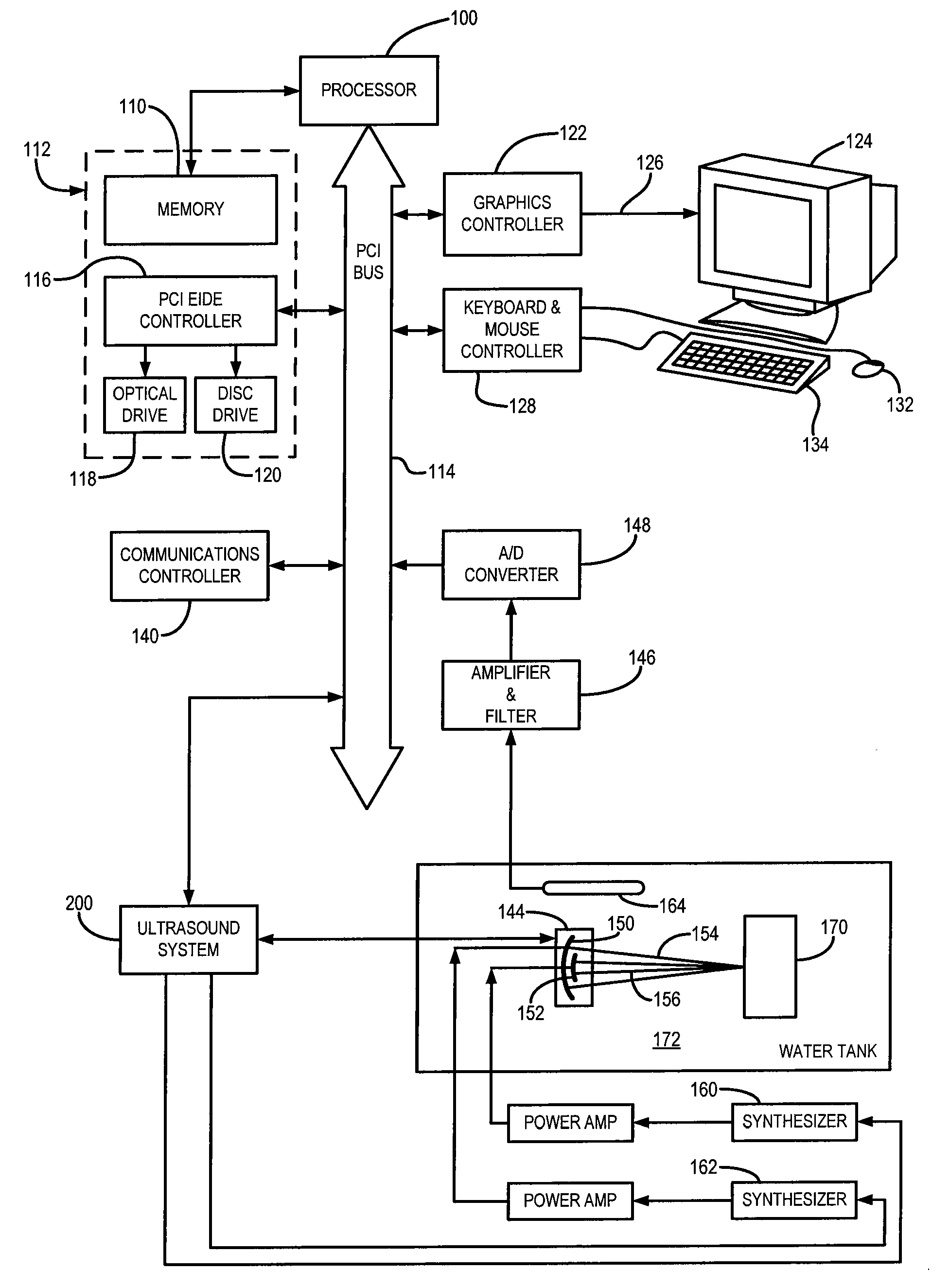
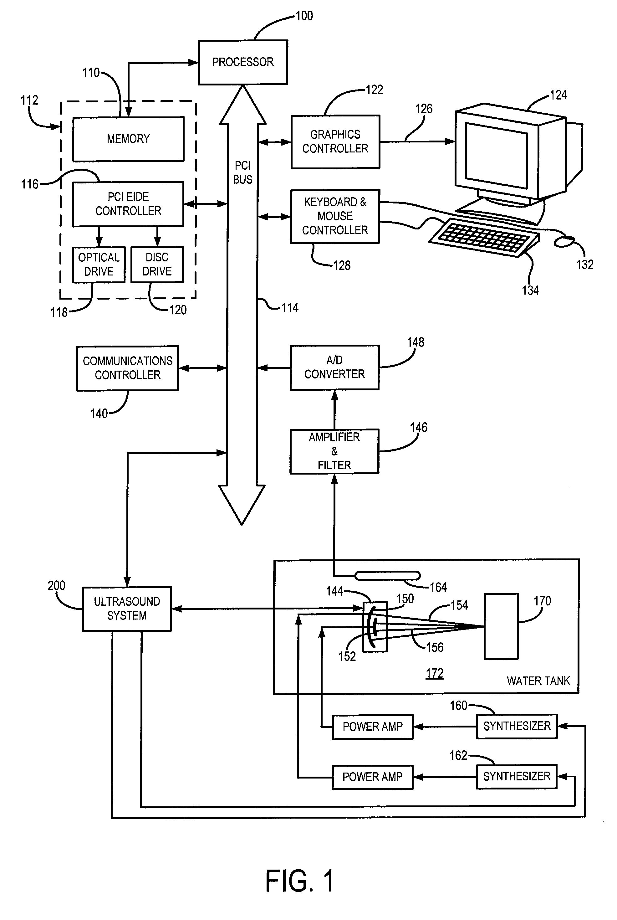
[0031]Referring particularly to FIG. 1, the preferred embodiment of the present invention employs an imaging system that includes a workstation. The computer workstation includes a processor 100 which executes program instructions stored in a memory 110 that forms part of a storage system 112. The processor 100 is a commercially available device designed to operate with one of the Microsoft Corporation Windows operating systems. It includes internal memory and I / O control to facilitate system integration and integral memory management circuitry for handling all external memory 110. The processor 100 also includes a PCI bus driver which provides a direct interface with a PCI bus 114.

[0032]The PCI bus 114 is an industry standard bus that transfers data between the processor 100 and a number of peripheral controller cards. These include a PCI EIDE controller 116 which provides a high-speed transfer of data to and from an optical drive 118 and a disc drive 120. A graphics controller 122...


PUM

PropertyMeasurementUnit
frequencyaaaaaaaaaa
acoustic forceaaaaaaaaaa
acoustic force frequencyaaaaaaaaaa

Abstract

A method for measuring variations of the surface of an object using acoustic energy in the audio range is provided. Imaging fine surface roughness on the order of few microns is achievable by using a vibroacoustography technique. This technique provides a method for imaging surface roughness on the basis of an ultrasound radiation force that stimulates acoustic emissions at an ultrasound standing wave field. The present invention may be employed as a tool for the nondestructive inspection and imaging of the surface variations of an object.

Description

CROSS-REFERENCE TO RELATED APPLICATIONS[0001]This application claims the benefit of U.S. Provisional patent application Ser. No. 60 / 933,642 filed on Jun. 7, 2007, and entitled “Method For Imaging Surface Roughness Using Acoustic Emissions Induced by Ultrasound”, which is herein incorporated by reference.STATEMENT REGARDING FEDERALLY SPONSORED RESEARCH[0002]This invention was made with government support under Grant No. EB000535 awarded by the National Institute of Biomedical Imaging and Bioengineering. The United States Government has certain rights in this invention.BACKGROUND OF THE INVENTION[0003]The field of the invention is ultrasound imaging methods and systems. More specifically, the field of the invention is ultrasonic nondestructive techniques for imaging the roughness of a surface.[0004]There are a number of modes in which ultrasound can be used to produce images of objects. The ultrasound transmitter may be placed on one side of the object and the sound transmitted throug...

Claims


Application Information

Patent Timeline
Patent Type & Authority Applications(United States)
IPC IPC(8): G01N29/14
CPCG01B17/08G01N29/14G01N2291/0289G01N2291/015G01N29/262
Inventor FATEMI, MOSTAFAMITRI, FARID G.
Owner MAYO FOUND FOR MEDICAL EDUCATION & RES
Why Eureka
Try Eureka