Plasma treatment apparatus
a treatment apparatus and plasma technology, applied in the direction of vacuum evaporation coating, chemical vapor deposition coating, coating, etc., can solve the problems of inability to obtain sufficient evaporation rate from these techniques, inability to use dc sputtering method which is usually used for forming metal films, and inability to stably form films with uniform film thickness and film quality, etc., to achieve uniform film thickness and/or film quality.
- Summary
- Abstract
- Description
- Claims
- Application Information
AI Technical Summary
Benefits of technology
Problems solved by technology
Method used
Image

Examples
embodiment 1
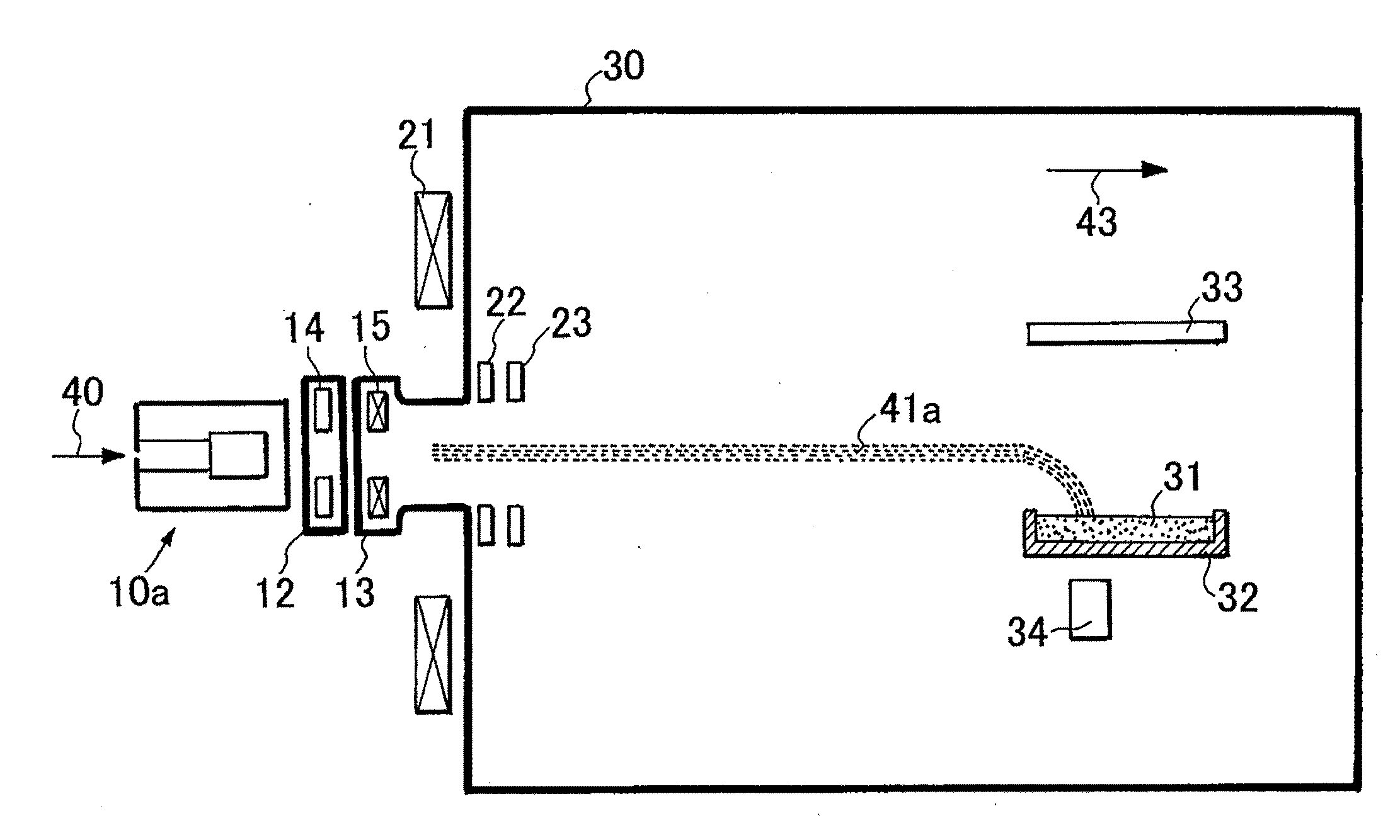
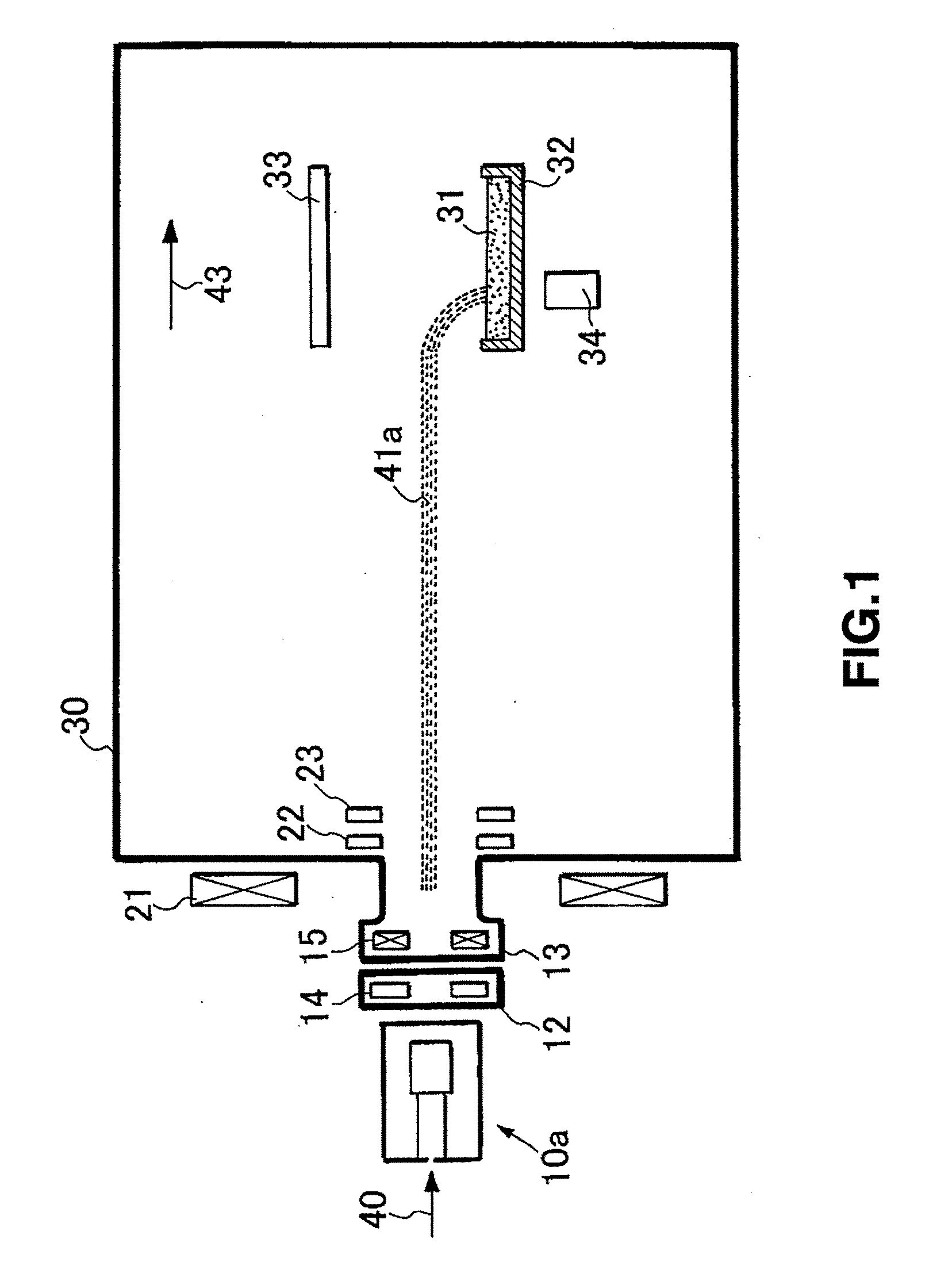
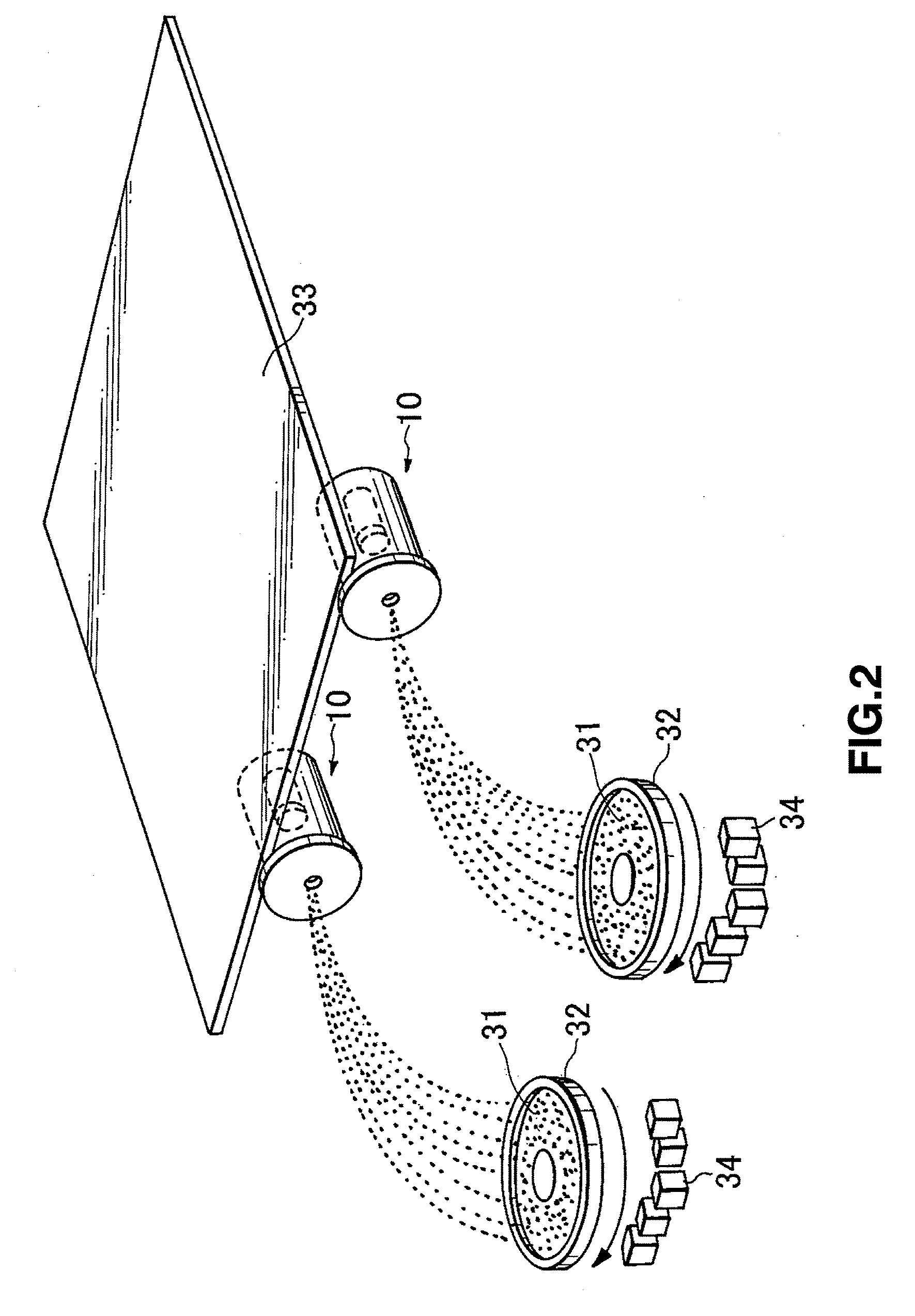
[0053]FIG. 1 is a side view of a schematic configuration of a film-forming apparatus according to Embodiment 1 of the present invention. FIG. 2 is a perspective view illustrating an aspect in which an insulation film is formed with the apparatus. However, in FIG. 2, a film-forming chamber and the like are omitted because FIG. 2 illustrates a view for describing the outline of the aspect in which the film is formed. FIG. 3 is an explanatory drawing on the generation and control of plasma generated by a UR-type plasma gun which is used in Embodiment 1.
[0054]In FIG. 1, a plasma gun 10a comprises an intermediate electrode 12 having an annular magnet 14, and an intermediate electrode 13 having an annular coil 15. A convergence coil 21 is arranged in between the plasma gun 10a and a film-forming chamber 30 which will be described later, so as to surround plasma discharged from the plasma gun 10a.
[0055]Though the configuration of the plasma gun 10a was described in FIG. 1, a plasma gun 10...
embodiment 2
[0075]In Embodiment 2 as well according to the present invention, a plurality of UR-type plasma guns including reflected electron return electrodes are used, but one of the UR-type plasma guns including the reflected electron return electrodes is grounded, and all other UR-type plasma guns including the reflected electron return electrodes are set at a floating state (not grounded). FIG. 6 illustrates the circuit diagram.
[0076]A working state of the plasma treatment apparatus at this time is illustrated in FIG. 7. Here, an evaporating material tray 32 is depicted in a state of being rotated by 90 degrees with respect to a horizontal line, for description, similarly to Embodiment 1 of the present invention. Structures arranged in downstream of electron current from the reflected electron return electrode, specifically, a short pipe 24, a second sheeting magnet 23 and a shield 34 for covering the inner wall of a film-forming chamber 30 are set at an electrically floating potential, wh...
embodiment 3
[0078]An insulation-film-forming apparatus according to Embodiment 3 of the present invention has the plurality of the UR-type plasma guns including the reflected electron return electrodes as described above, and sets the potential of a certain particular UR-type plasma gun including a reflected electron return electrode at a floating potential.
[0079]As is understood from the above described description, the above described plasma treatment apparatus having the plurality of the UR-type plasma guns including the reflected electron return electrodes sets the potential of the certain particular UR-type plasma gun including the reflected electron return electrode at the floating potential, and can thereby prevent reflected return electron currents of adjacent UR-type plasma guns from flowing into the reflected electron return electrode, or the electron current relating to the UR-type plasma gun from flowing into the adjacent reflected electron return electrodes. Therefore, insofar as t...
PUM
| Property | Measurement | Unit |
|---|---|---|
| electric potentials | aaaaa | aaaaa |
| density | aaaaa | aaaaa |
| magnetic field | aaaaa | aaaaa |
Abstract
Description
Claims
Application Information
 - R&D
- Intellectual Property
- Life Sciences
- Materials
- Tech Scout
- Unparalleled Data Quality
- Higher Quality Content
- 60% Fewer Hallucinations
Browse by: Latest US Patents, China's latest patents, Technical Efficacy Thesaurus, Application Domain, Technology Topic, Popular Technical Reports.
© 2025 PatSnap. All rights reserved.Legal|Privacy policy|Modern Slavery Act Transparency Statement|Sitemap|About US| Contact US: help@patsnap.com