
1200°C Film Resistor

a film resistor and resistor technology, applied in the field of electric temperature sensors, can solve problems such as the physical behavior of the temperature measurement element as a disturban

Active Publication Date: 2009-05-07
HERAEUS NEXENSOS GMBH
View PDF37 Cites 21 Cited by
  • Summary
  • Abstract
  • Description
  • Claims
  • Application Information

AI Technical Summary

Benefits of technology

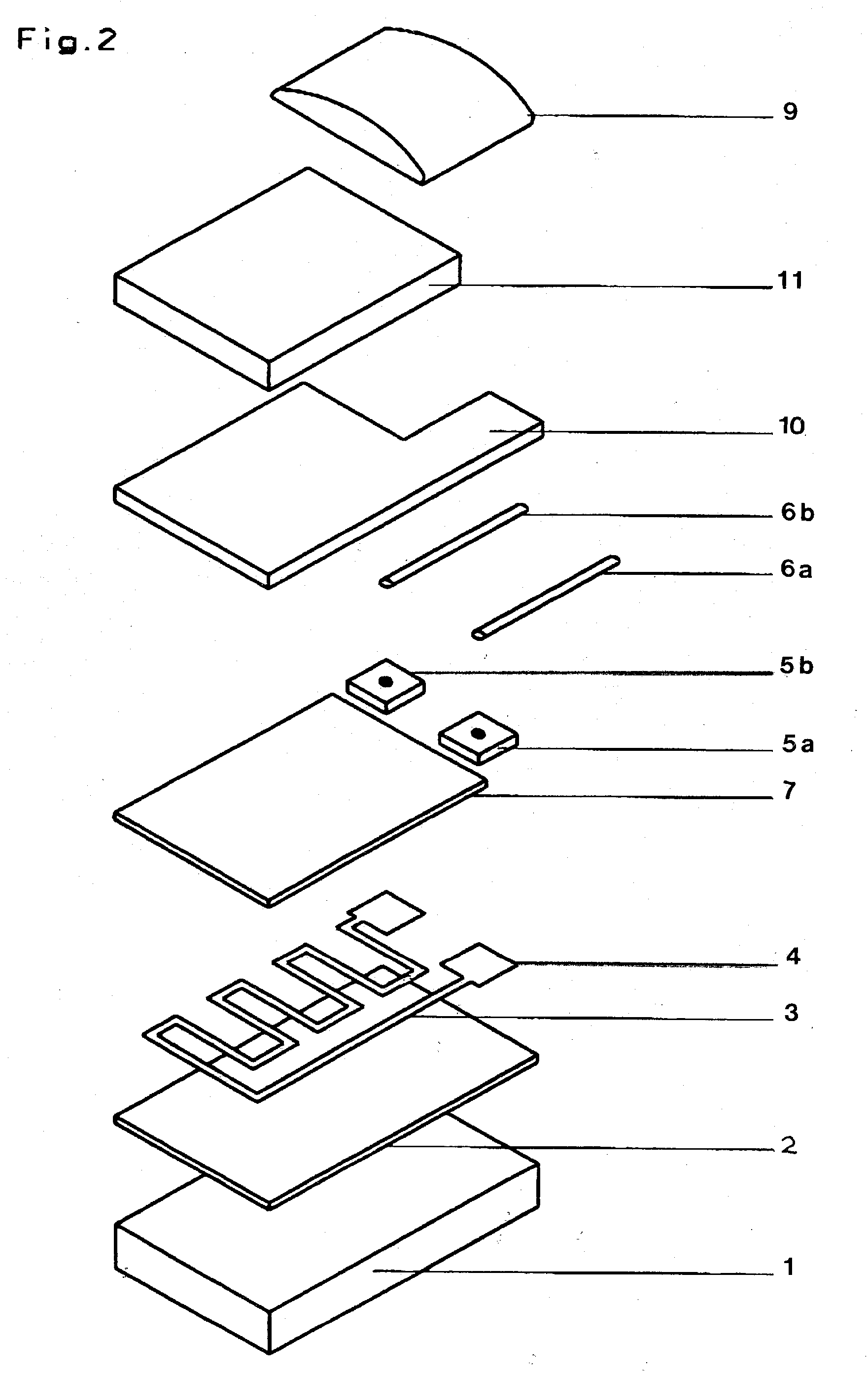
[0014]In one particularly simple embodiment, a glass ceramic doped with metal or a glass ceramic is used, which above 750° C. is electrically conductive or is an ion conductor, wherein the glass ceramic, optionally doped with metal, is covering the ceramic film on the resistance film beyond the ceramic film connecting the cathode of the resistance film pattern. The glass ceramic provided with a cathode potential or grounded in this way prevents the migration of cations to the Pt measurement resistor. In particular, a wetting of the cathodically connected terminal field (pad) with glass ceramic results. Here, the glass ceramic, which is optionally doped with metal, contributes to stress relaxation of the terminal wire attached to the terminal pad.
[0032]Advantageously, an economical production as well as a long service life of the temperature-dependent resistor have resulted.

Problems solved by technology

Also, if the diffusion blocking film allows the oxygen to access the dielectric film and thus essentially prevents an attack of metal ions coming free from the glass film on the platinum film, this can still, nevertheless, under extreme environmental conditions lead to an attack on the platinum film, so that its physical behavior as a temperature measurement element is disrupted.
For this sensor, however, it must always be taken care that the cathode is connected correctly electrically, because a mix-up of the electrical connections leads to destruction of the sensor.

Method used


Image

  • 1200°C Film Resistor
  • 1200°C Film Resistor
  • 1200°C Film Resistor

Examples


Embodiment Construction

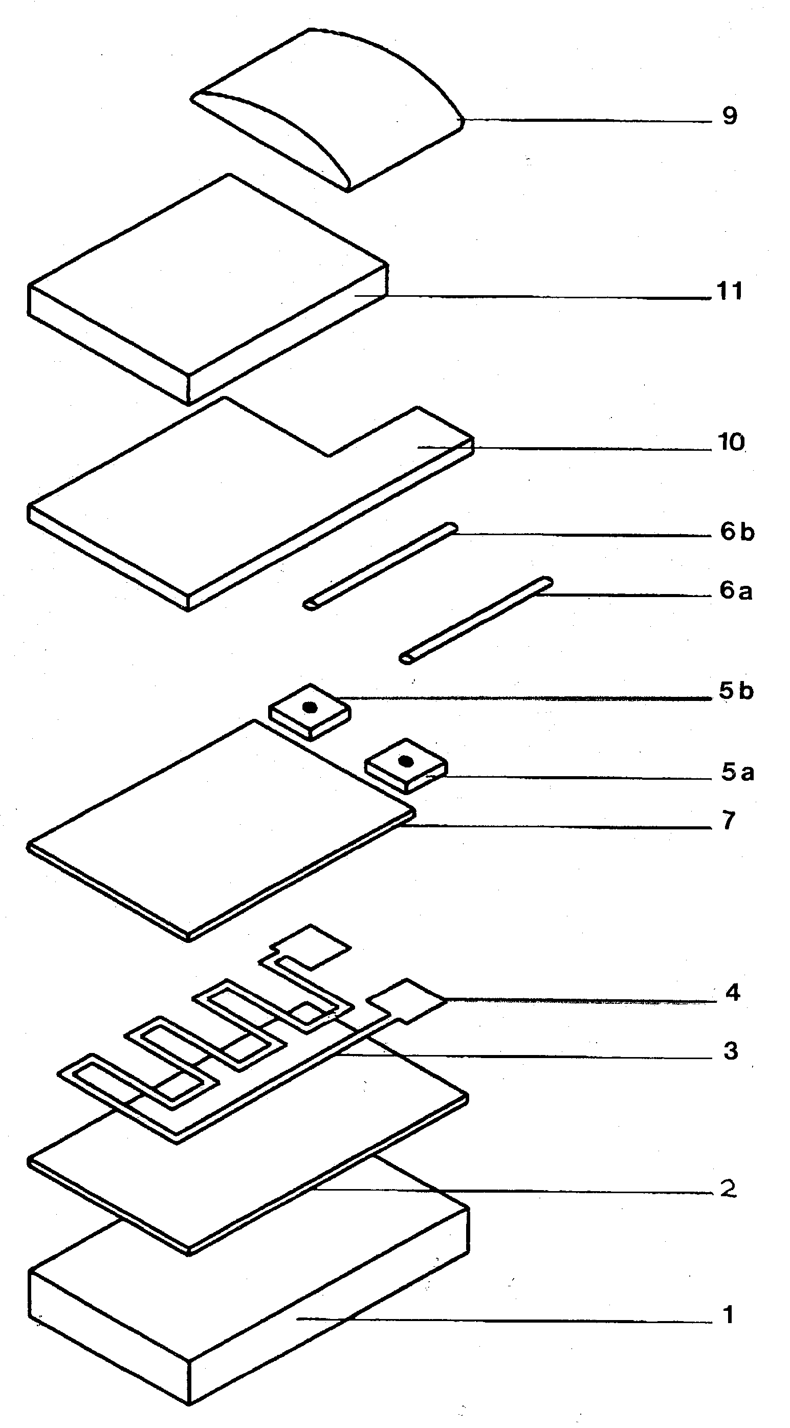
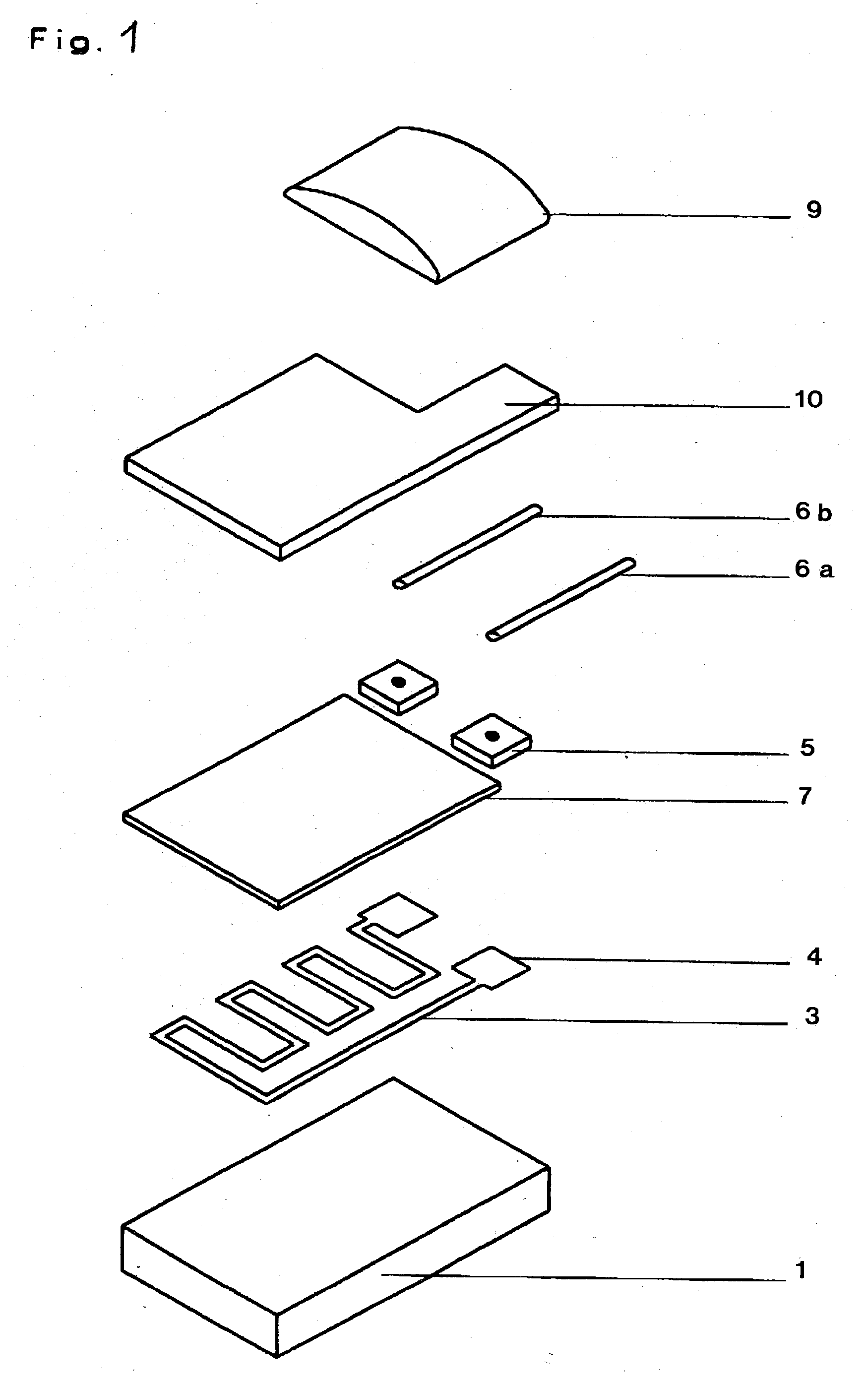
[0050]According to FIG. 1, the resistance film 3 serving as a measurement resistor is located as a thin film on a planar surface of a sapphire 1. The resistance film 3 is constructed in the form of a meander with contact pads 4, as known, for example, from German Patent DE 40 26 061 C1 or European Patent EP 0 471 138 B1. The contact pads 4 are made of the same material as the resistance film 3. The resistance film 3 is provided on its side facing away from the substrate 1 with a diffusion blocking film 7 as the intermediate layer 7, which is covered, for its part, with a passivation layer 10 made of quartz glass ceramic.

[0051]Due to this passivation layer 10, the sensitive structure of the platinum-containing resistance film 3 is effectively protected against atmospheric poisons of the environment. In such a multi-layer structure, for high purity of the ceramic and quartz glass components of the quartz glass ceramic 10, cations that are very harmful for the platinum resistance film ...


PUM

PropertyMeasurementUnit
Temperatureaaaaaaaaaa
Sheet resistanceaaaaaaaaaa

Abstract

For production of a high-temperature sensor, in which a platinum resistance film is applied on a metal-oxide substrate, in particular sapphire or a ceramic plate, and a ceramic intermediate layer is laid on the resistance film, a self-supporting cover, in particular a ceramic or glass-ceramic cover, is bonded on the ceramic intermediate layer or a glass ceramic is mounted on the intermediate layer over its entire surface. Advantageously, the glass ceramic is electrically conductive or an ion conductor above 750° C. and is laid on up to the cathode of the resistance film up to beyond the intermediate layer. In particular, the cover is bonded with a metal-doped glass ceramic, which is laid on the cathode of the resistance film up to beyond the intermediate layer. Preferably, the electrically insulating intermediate layer is coated with a glass ceramic or a glass ceramic doped with metal, which coating has a resistance of at most one megaohm per square at 850° C. or above.

Description

BACKGROUND OF THE INVENTION[0001]The present invention relates to an electrical temperature sensor with a resistance film pattern as a measurement resistor provided with electrical terminals on an electrically insulating surface of a substrate, in particular made of ceramic, wherein the resistance film pattern is covered with a diffusion blocking film.[0002]From International Patent Application Publication No. WO 92 / 15101 a fast platinum metal temperature sensor is known, having a platinum resistance film applied on a ceramic substrate and a passivation layer is applied over this resistance film, wherein the passivation layer is formed as a double film made of a ceramic film and a glass film.[0003]For production of such a temperature-dependent resistor as a temperature sensor, the resistance film (Pt meander) is applied as a thick film on a substrate having a surface made of electrically insulating material, wherein the outer surface of the resistance film is covered by a layer made...

Claims


Application Information

Patent Timeline
IPC IPC(8): H01C7/02C03B29/00
CPCG01K1/10H01C17/06526H01C17/02G01K7/183H01C3/04H01C7/02
Inventor WIENAND, KARLHEINZLOOSE, THOMASSANDER, MARGIT
Owner HERAEUS NEXENSOS GMBH
Learn More