Eureka AIR delivers breakthrough ideas for toughest innovation challenges, trusted by R&D personnel around the world.

Large mode area fiber amplifiers with reduced stimulated brillouin scattering

Active Publication Date: 2009-05-07
OFS FITEL LLC
View PDF18 Cites 6 Cited by
  • Summary
  • Abstract
  • Description
  • Claims
  • Application Information

AI Technical Summary

Benefits of technology

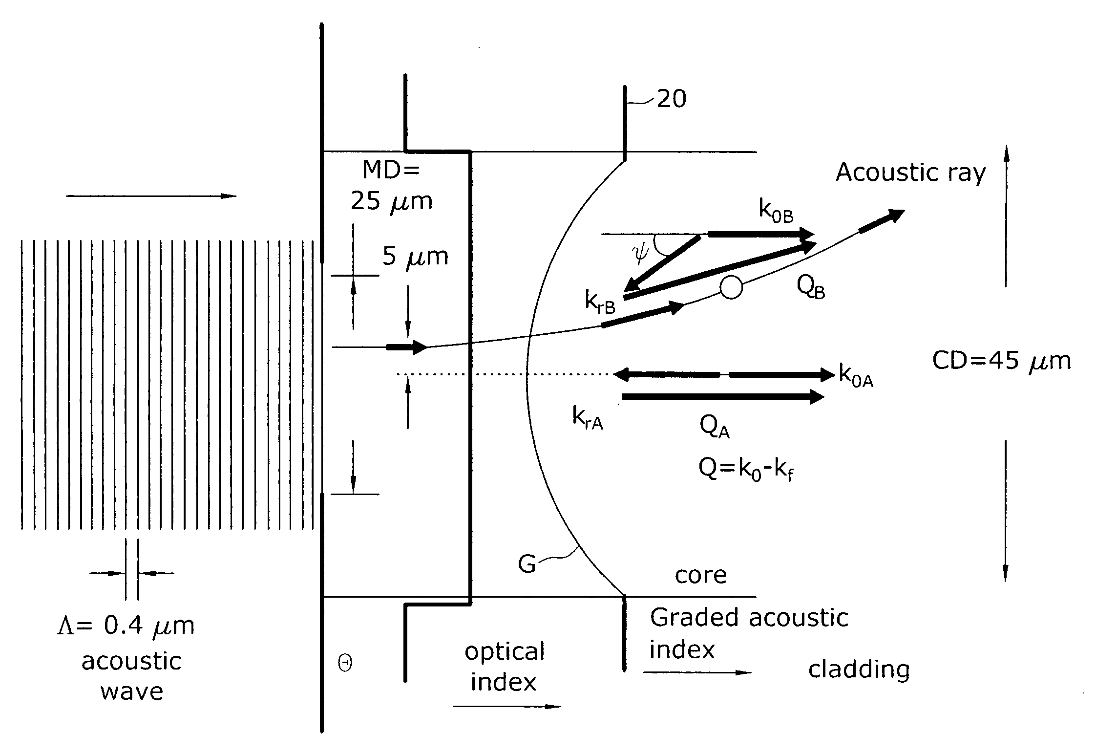
[0016]In another embodiment of the present invention, the optical refractive index has a large depression in the central region of the core, thereby producing a ring-like core structure. The resultant optical mode is primarily localized in the ring region of the core (i.e., the “edges” of the core) and will therefore exhibit the desired large mode area. The acoustic index is designed to have a low value where the optical index is high (i.e., in the ring region), and a high value where the optical index is low. This acoustic index structure localizes the thermal phonon away from the optical mode and facilitates the refraction of the acoustic energy away from the ring region and into regions where there is little optical energy. As long as the width of the ring remains less than the phonon decay length, the acoustic energy will refract out of the optical field and minimize the generation of SBS.
[0017]In yet another embodiment of the present invention, the higher order modes (HOM) in a suitably-designed optical fiber exhibit very large effective areas and may also be considered LMA fibers suitable for use as fiber amplifiers with reduced SBS. A HOM fiber exhibits a highly-structured optical intensity profile that extends over a large core size (e.g., radii greater than approximately 40 μm have been demonstrated). An acoustic index profile for an inventive HOM fiber thus excludes the thermal acoustic modes from the regions of the core occupied by the optical mode and refracts the acoustic energy away from regions occupied by the optical mode, thereby reducing the acousto-optic interaction and increasing the SBS threshold in HOM fibers.

Problems solved by technology

Hence, this light is lost from the waveguide and cannot contribute to the onset of SBS; the SBS threshold is increased further as a result.

Method used


Image

  • Large mode area fiber amplifiers with reduced stimulated brillouin scattering
  • Large mode area fiber amplifiers with reduced stimulated brillouin scattering
  • Large mode area fiber amplifiers with reduced stimulated brillouin scattering

Examples


Embodiment Construction

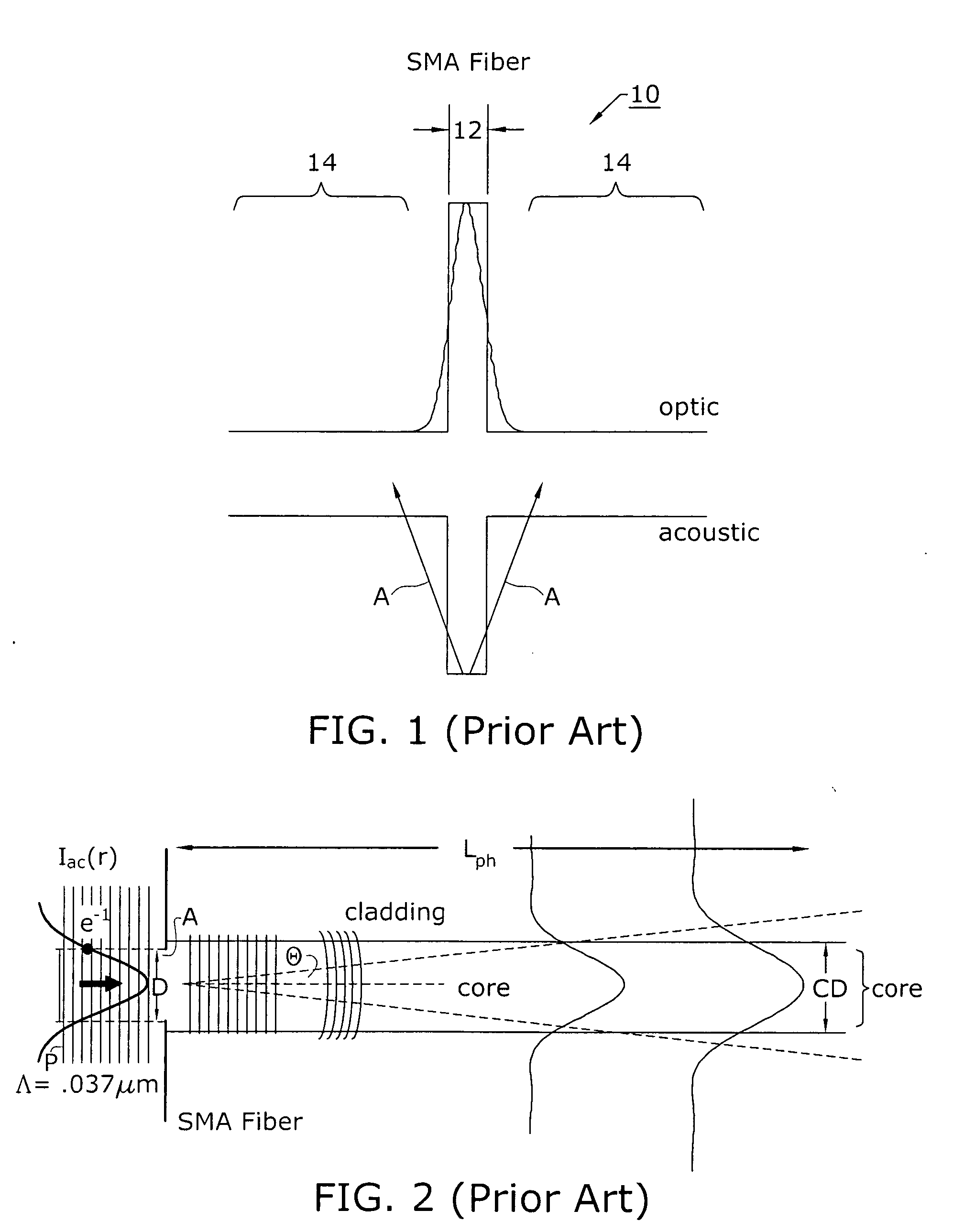
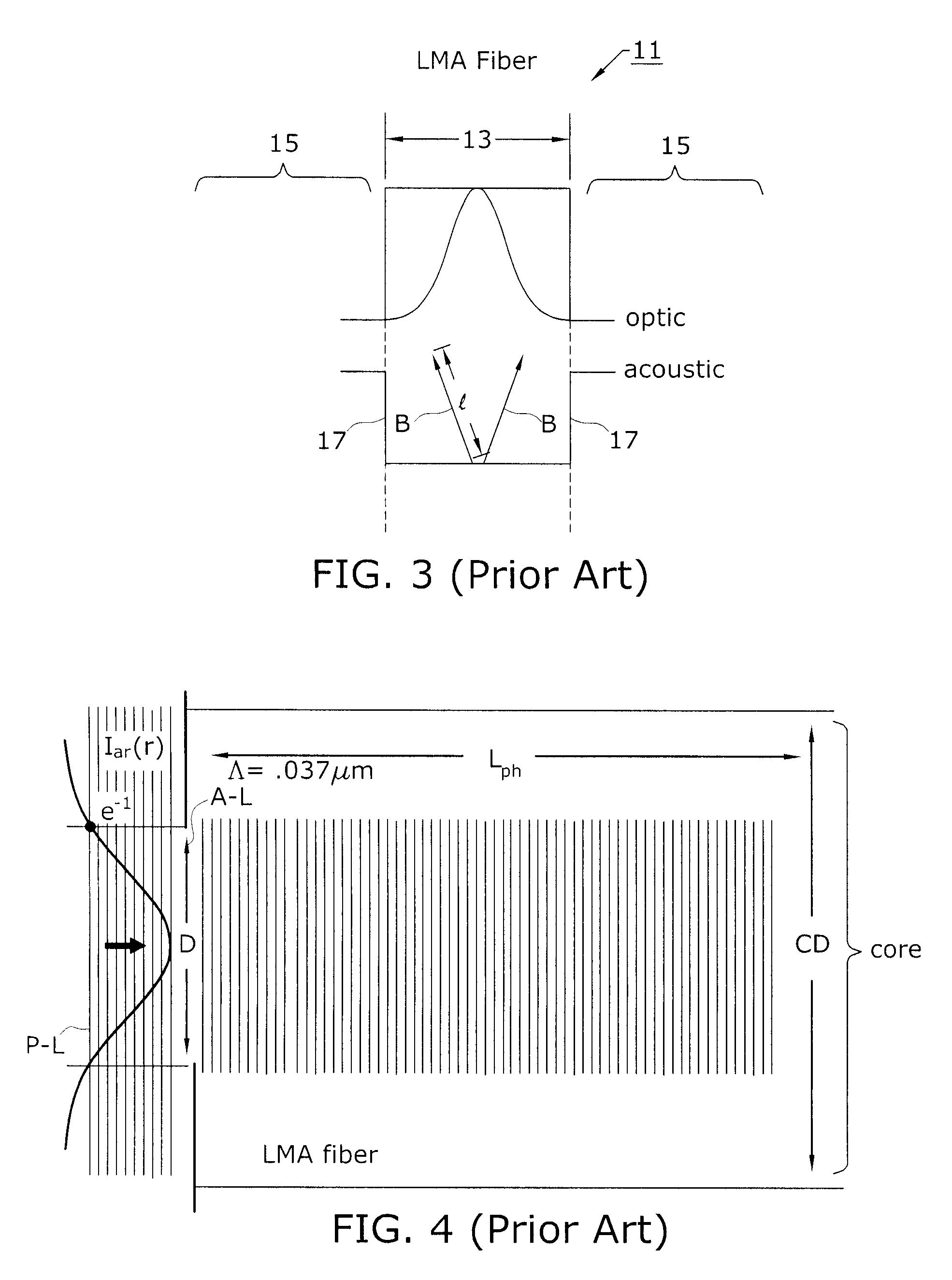
[0030]As will be discussed in detail below, the ability to reduce stimulated Brillouin scattering (SBS) in large mode area (LMA) fibers in accordance with the present invention involves the study and understanding of two separate design considerations. Firstly, it is required that the central core region of the LMA be configured to exhibit a structured acoustic index that will exclude the thermally-generated acoustic fields (phonons) from the central portion of the core (where the majority of the optical mode resides), reducing the overlap integral between the optic and acoustic components as well as the thermal Brillouin light scattering cross-section. It is this thermal Brillouin light scattering that seeds the SBS process in a manner similar to that already described for SMA fibers (thus increasing the threshold at which SBS is initiated). Inasmuch as desired acoustic index structure is accomplished by a relatively minor contrast in acoustic index between regions, it is unnecessa...


PUM


Abstract

A large mode area fiber amplifier suitable for high power applications includes a core region specifically configured to allow for high power operation while also limiting the amount of SBS that is generated. The composition of the core region is selected to include a dopant (such as aluminum) in selected areas to reduce the acoustic refractive index of the core and limit the spatial overlap between the acoustic and optical fields. The acoustic refractive index is also structured so that the acoustic field is refracted away from the central core area. In one embodiment, the core may comprise a depressed index center portion and surrounding ring core area, with the center portion including the aluminum doping and the ring formed to have a diameter less that the phonon decay length for the operating wavelength(s).

Description

TECHNICAL FIELD[0001]The present invention relates to large mode area (LMA) optical fibers utilized in fiber amplifiers and, more particularly, to LMA optical fibers including selected regions with a structured acoustic refractive index profile within the optical core section that is designed to exclude / refract acoustic energy away from regions occupied by the optical mode, thereby reducing stimulated Brillouin scattering (SBS).BACKGROUND OF THE INVENTION[0002]Laser systems including fiber amplifiers are commonly used in many applications, including telecommunications applications and high-power military and industrial fiber optic applications. In operation, the propagating optical signal from a laser source is introduced in the core region of a section of optical fiber and is amplified through the use of an optical “pump” signal. The pump is of a predetermined wavelength that will interact with particular dopants included in the core region of the fiber amplifier (typically rare ea...

Claims


Application Information

Patent Timeline
IPC IPC(8): G02B6/028
CPCG02B6/02009G02B6/02023H01S3/06754H01S3/06708H01S3/0672G02B6/03694
Inventor DIGIOVANNI, DAVID J.MERMELSTEIN, MARC D.
Owner OFS FITEL LLC
Why Eureka
Eureka Blog
Learn More