[0003]
Fiber lasers are defined as a laser with an optical fiber as the gain media. In most cases, the gain medium is a fiber doped with rare-earth ions such as erbium,
neodymium, ytterbium,
thulium, or
praseodymium, and one or several laser diodes are used for pumping of the doped fiber.
Fiber laser can be end-pumped or side-pumped. Fiber lasers have many special attractions, particularly for use in the
telecommunications field. Some of these special attractions are: a compact and rugged setup, provided that the whole laser cavity is built only with fiber components such as e.g. fiber Bragg gratings and fiber couplers, a large
gain bandwidth due to strongly broadened laser transitions in glasses, enabling wide
wavelength tuning ranges and / or the generation of ultrashort pulses, broad spectral regions with good pump absorption, making the exact pump wavelength uncritical,
diffraction-limited beam quality (when single-mode fibers are used), the potential to operate with very small pump powers, the potential for very high output powers (several kilowatts with double-clad fibers) due to a
high surface-to-volume ratio (avoiding excessive heating) and the guiding effect, which avoids thermo-optical problems even under conditions of significant heating, and the ability to operate even on very “difficult” laser transitions (e.g. of up-conversion lasers) due to the ability to maintain high pump intensities over long lengths
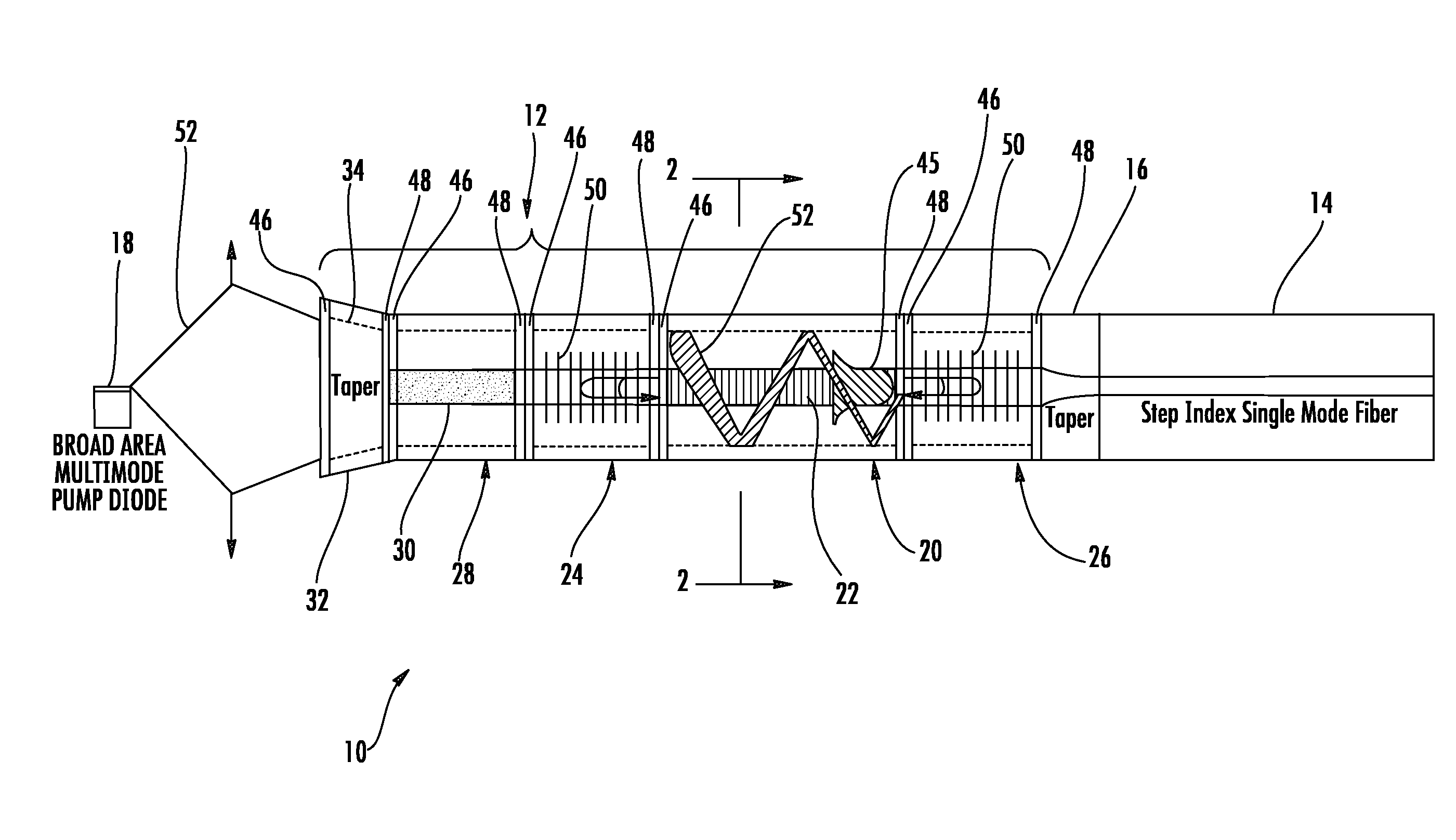
[0005]The present invention seeks to solve several of the problems commonly encountered in the prior art by utilizing a unique large mode area
photonic crystal fiber structure which reduces non-linear effects, and has high gain and pump absorption per unit length, and an active absorptive section between the lasing cavity and the pump source that absorbs the emission wavelength and prevents it from reflecting back into the pump source. The large mode area fiber allows the invention to also takes
advantage of inexpensive broad area multi-mode diodes, which have a longer duty life and
higher power than single-mode diodes.
[0008]Large mode area fibers can also be created using
photonic crystal fibers (PCFs).
Photonic crystal fiber (PCF) (also called
holey fiber or
microstructure fiber) is an optical fiber, which derives its
waveguide properties not from a spatially varying material composition, but from an arrangement of very tiny air holes, which extend longitudinally in a symmetric pattern through the whole length of fiber. Such air holes can be obtained by creating a fiber preform with holes made by stacking capillary tubes (stacked tube technique). Soft glasses and polymers also allow the fabrication of pre-forms for PCF's by
extrusion. There is a great variety of hole arrangements, leading to PCF's with very different properties. A typical PCF has a
regular array of hexagonally placed air holes surrounding a
solid core, which supports guided
modes in the
solid core by providing a composite cladding consisting of regular air holes in a glass background, the air holes having a lower
effective refractive index than that of the core. To reduce the number of guided
modes, the state-of-the-art PCF designs employ small air holes with a hole-
diameter-to-
pitch ratio d / Λ of less than 0.1. In this regime, the PCF is very weakly guiding, leading to a high degree of environmental sensitivity. As a result, robust single-mode propagation in PCFs has also been limited to a MFD of approximately 28 μm, a level similar to that of conventional fiber, which is not surprising considering the similarity in the principle behind the two approaches.
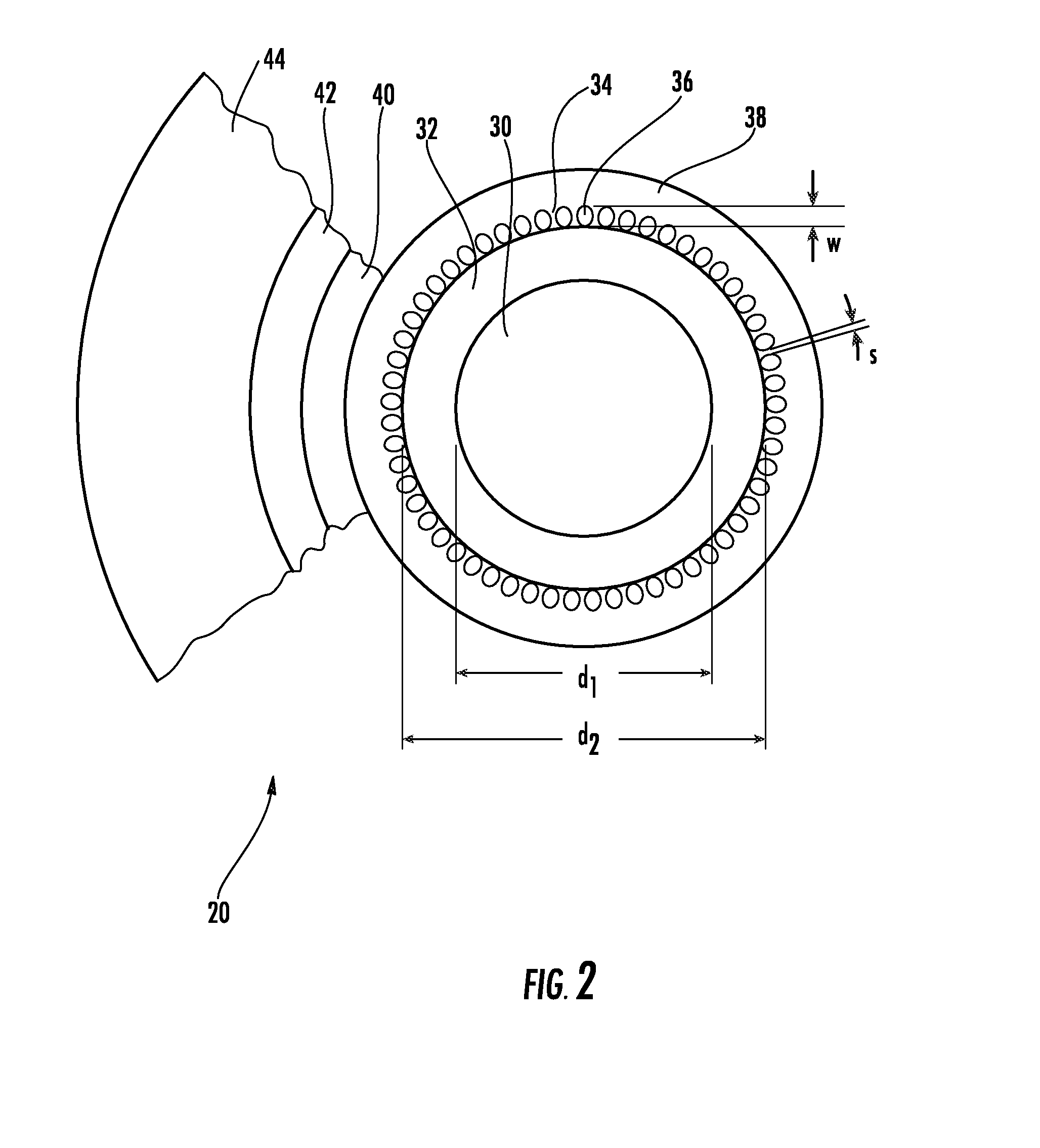
[0010]The single-mode fiber laser of the present invention comprises a single mode holding, large mode area
photonic crystal fiber assembly having a large mode area silica core, a first silica cladding and a second
air channel cladding. Preferably, the second cladding comprises a circular layer of coaxial channels having a very low
refractive index as compared to the core and the first cladding such that the first cladding has a relatively
high numerical aperture (NA>0.4). The large change in
refractive index between the first cladding and second cladding provides an effective single mode holding
waveguide for low loss transmission and pumping of a fiber laser.
[0012]A broad area, multi-mode pump source is configured to pump multi-mode light into a large mode area tapered input section. The multi-mode pump light propagates through the fiber assembly, cladding-pumping the gain section and producing a stimulated single-mode emission at the desired operating wavelength. The absorptive section, located between the tapered input section and the first reflective section, absorbs emissions at the operating wavelength and prevents operating emissions from reflecting back into said pump source. On the output end of the large mode area fiber assembly, a tapered transition fiber directs the stimulated single-mode emission from the large mode area core into a smaller
diameter single mode core. The output of the tapered transition fiber is coupled to a conventional step-index single-mode output fiber.
[0013]Accordingly, among the objects of the instant invention are: the provision of single-mode emission fiber laser having a 980 nm continuum emission ideally suited for pumping erbium-doped gain media; the provision of a single-mode fiber laser that utilizes a high-power (1-10 W), broad-area, multi-mode pump source to cladding pump a large mode area fiber and produce a high-power single-mode
stimulated emission; and the provision of a fiber laser having an active fiber section on the pump side of the lasing cavity to absorb emissions in the operating wavelength and prevent them from reflecting back into the pump source.

