Cascade laser

a laser and cascade technology, applied in lasers, fiber transmission, transmission, etc., to achieve the effect of low nonlinearity and large mode area

Inactive Publication Date: 2009-10-22
COMMONWEALTH OF AUSTRALIA
View PDF6 Cites 16 Cited by
  • Summary
  • Abstract
  • Description
  • Claims
  • Application Information

AI Technical Summary

Benefits of technology

[0036]In an embodiment, the fiber can have a helical core allowing a large mode area for low nonlinearity in a large diameter cladding which otherwise couldn't be bent.

Problems solved by technology

Advantageously, this iterative process permits, in some embodiments, the use of otherwise insufficiently bright pump sources to achieve laser action.

Method used


Image

  • Cascade laser
  • Cascade laser
  • Cascade laser

Examples


example

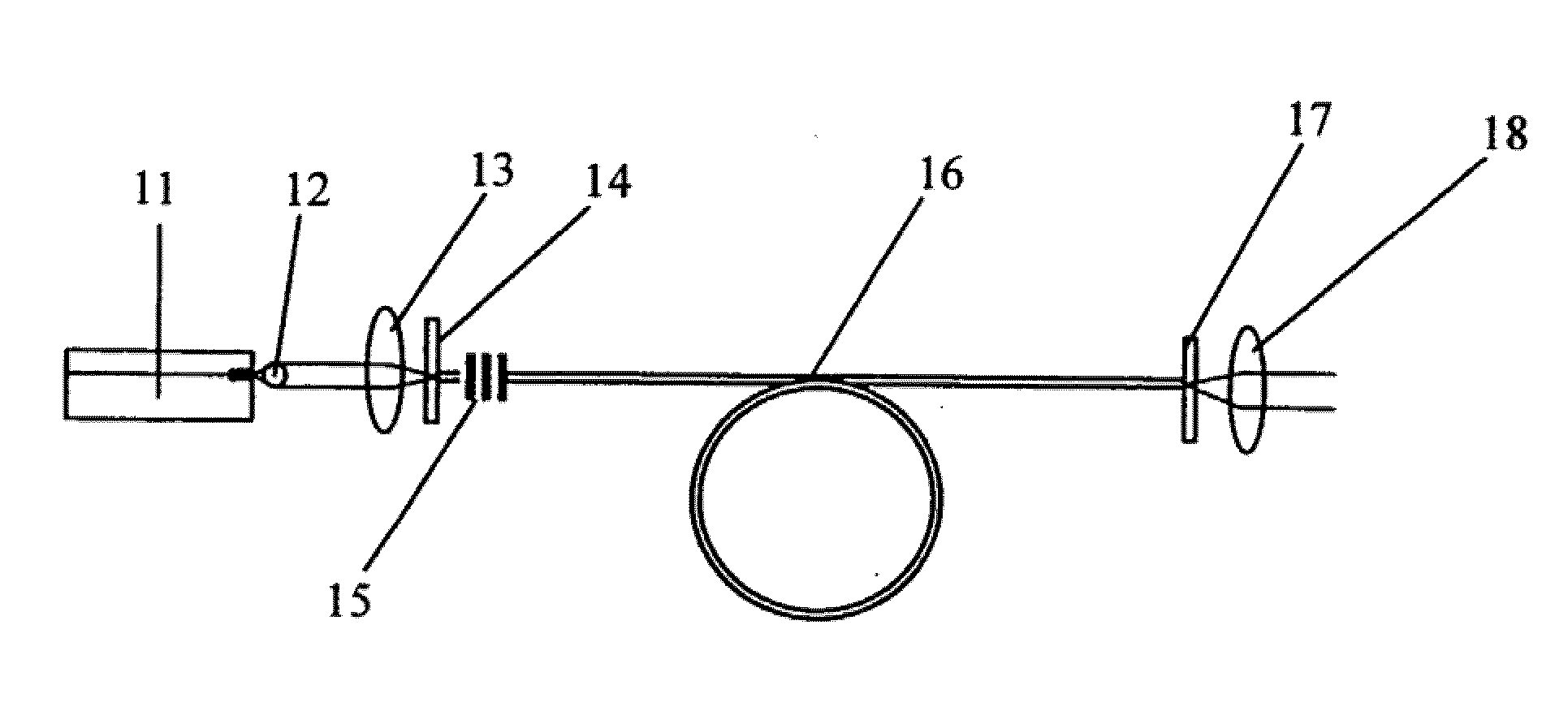
[0086]We report the first demonstration of resonant in-fiber pumping of the Ho3+ ion from one embodiment of a fiber laser having a double clad laser within a double clad laser. The fiber was designed to have a thulium outer core, and a holmium inner core. These dopants were selected in this first demonstration because Tm3+ displays efficient laser operation at ˜2 μm when pumped at 790 nm. This operating wavelength is close to the peak of the 5I7 absorption band of Ho3+ which lases at 2.1 μm. To demonstrate the concept we employed an external resonator which was designed to be highly resonant at the thulium emission wavelength. The output coupler mirror was designed to outcouple a low percentage (˜20%) of the light produced from the Ho3+ laser transition.

[0087]The fiber was designed and fabricated at the Optical Fiber Technology Centre using MCVD and solution doping. The fiber preform was fabricated using a substrate tube which was placed in a glass working lathe and 12 layers of gla...


PUM


Abstract

Disclosed is an optical fiber that includes an inner core having a concentration of at least one laser active material, the inner core being adapted to operate in a single mode manner; and an outer core disposed about the inner core having a concentration of at least one laser active material. The outer core being adapted to operate in a multimode manner, a cladding disposed about the outer core; and an outer cladding is disposed about the cladding adapted to substantially confine pump light within the cladding.

Description

PRIORITY CLAIM[0001]The present application is a Continuation-in-Part application of copending International Patent Application Serial No. PCT / AU2007 / 001597, filed Oct. 18, 2007; which application claims the benefit of Australian Patent Application Serial No. 2006905778, filed Oct. 18, 2006; all of the foregoing applications are incorporated herein by reference in their entireties.TECHNICAL FIELD[0002]The present invention relates generally to optically pumped lasers, and particularly but not exclusively to optically pumped waveguide lasers.BACKGROUND ART[0003]Fiber lasers or amplifiers comprising a doped fiber core with a laser active material, the core pumped with a single transverse mode pump source such as a diode laser or a Ti:Sapphire laser are known. A problem with this design is that the cost of a single transverse mode pump source per unit of pump power is very high making high power sources based on core pumped fibers impractical. Furthermore lasers and amplifiers construc...

Claims


Application Information

Patent Timeline
Patent Type & Authority Applications(United States)
IPC IPC(8): H01S3/30H01S3/00G02B6/036
CPCG02B6/02366H01S2302/00G02B6/03638G02B6/03661H01S3/06716H01S3/0672H01S3/06737H01S3/06741H01S3/094003H01S3/094007H01S3/09403H01S3/0941H01S3/161H01S3/1611H01S3/1616G02B6/03633
Inventor LANCASTER, DAVID GEORGEBENNETTS, SHAYNE PETER
Owner COMMONWEALTH OF AUSTRALIA
Why Eureka
Try Eureka