Method of fabrication of low-bend-loss single mode fibers of very large mode areas

a single-mode fiber and large-area technology, applied in the field of fabrication of single-mode fibers of very large-area mode areas, can solve the problems of low value of mode area when bent, poor maintenance of large-area mode areas, thermal and optical damage, etc., and achieves large-area mode, reduces mode loss and modal deformation, and robust single-modedness.

Active Publication Date: 2017-03-14
STC UNM
View PDF6 Cites 8 Cited by
  • Summary
  • Abstract
  • Description
  • Claims
  • Application Information

AI Technical Summary

Benefits of technology

[0007]In one embodiment, the present invention provides a novel unidirectionally-graded refractive index profile (UGRIP) optical fiber design based on a material index gradient that yields robust single-modedness, large mode areas, and effective suppression of HOMs (higher order modes). The present invention reduces mode loss and modal deformation, particularly in the lowest order mode, that inevitably occurs during bending of conventional “step index” (SI) fibers and leakage channel optical fibers (LCFs). These fibers will in general consist of a core whose average refractive index is generally higher than that of the cladding layers surrounding it; the core region is the primary region containing the amplified light in laser and amplifier fibers.

Problems solved by technology

Single-mode large mode area (LMA) fibers, which are important for high power fiber lasers, can maintain large mode areas when straight, but are poor at maintaining large mode areas when bent.
Likewise, very large mode area (VLMA) fibers that have been fabricated so far have extremely high mode losses and low values for mode areas when bent.
In addition, in a single-mode fiber amplifier or laser, limitations in scaling of the output powers come from the high intensities in the fiber, which can cause thermal and optical damage and also limit power scaling due to the onset of various nonlinear mechanisms.

Method used


Image

  • Method of fabrication of low-bend-loss single mode fibers of very large mode areas
  • Method of fabrication of low-bend-loss single mode fibers of very large mode areas
  • Method of fabrication of low-bend-loss single mode fibers of very large mode areas

Examples


Embodiment Construction

[0038]Detailed embodiments of the present invention are disclosed herein; however, it is to be understood that the disclosed embodiments are merely exemplary of the invention, which may be embodied in various forms. Therefore, specific structural and functional details disclosed herein are not to be interpreted as limiting, but merely as a representative basis for teaching one skilled in the art to variously employ the present invention in virtually any appropriately detailed method, structure or system. Further, the terms and phrases used herein are not intended to be limiting, but rather to provide an understandable description of the invention.

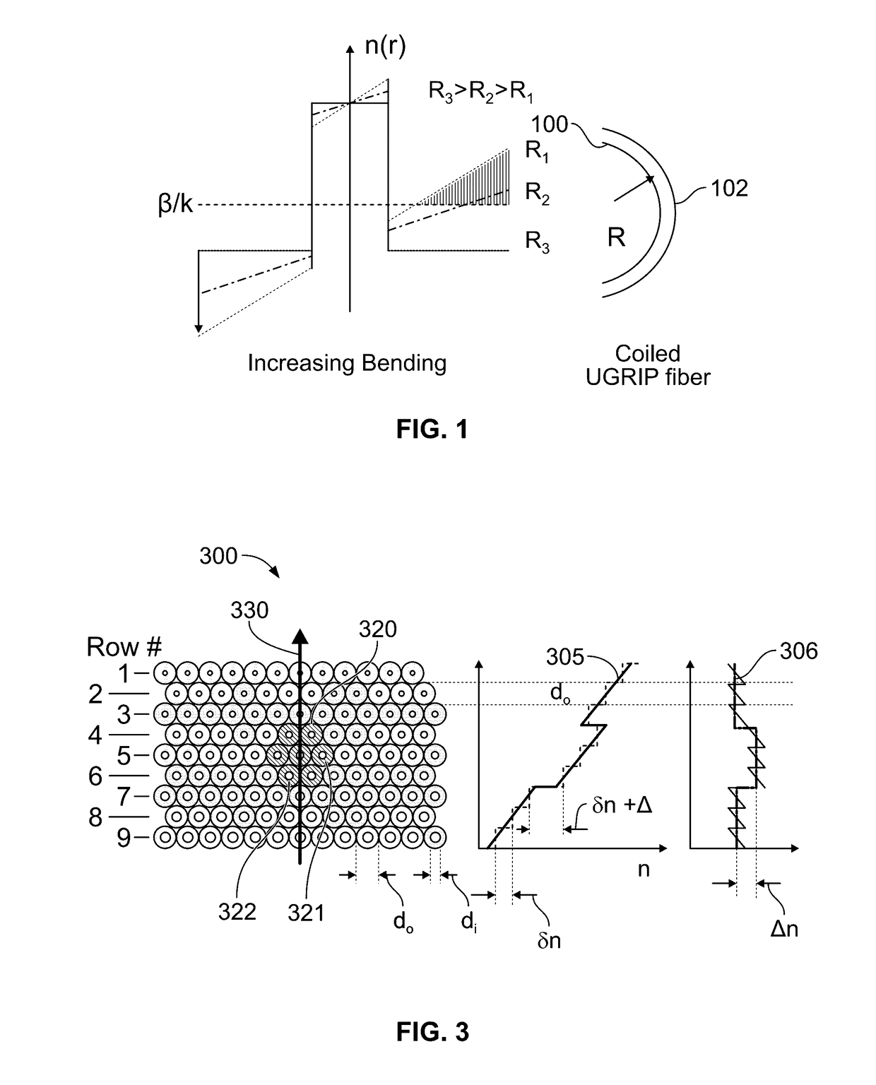
[0039]Optical fiber bend loss is related to the radius of curvature R of a typical step index fiber. When the actual radius of curvature approaches a critical value Rc, the bend loss increases sharply from negligible values to intolerably large values, implying very large bend losses when fibers with Aeff>1000 μm2 are not kept straight. An ...


PUM

PropertyMeasurementUnit
mode areaaaaaaaaaaa
mode field diametersaaaaaaaaaa

Abstract

The present invention provides an optical fiber and method of making the same. The optical fiber includes a body for transmitting light. The body has an anisotropic refractive index wherein the anisotropic refractive index offsets changes in the refractive index of the fiber caused by bending the fiber. The fiber body may further include a core and cladding.

Description

RELATED APPLICATIONS[0001]This application claims the benefit of U.S. Provisional Application No. 61 / 953,886, filed Mar. 16, 2014 and herein incorporated by reference.STATEMENT REGARDING FEDERALLY SPONSORED RESEARCH & DEVELOPMENT[0002]This invention was made with government support under an AFOSR Grant entitled “Optoelectronics Research Center”, AFOSR Grant FA9550-12-1-0049 and ARO HBCU / MI Grant W911NF1310111, Proposal #62755-EL-REP. The government has certain rights in the inventionINCORPORATION BY REFERENCE OF MATERIAL SUBMITTED ON A COMPACT DISC[0003]Not applicable.BACKGROUND OF THE INVENTION[0004]Single-mode large mode area (LMA) fibers, which are important for high power fiber lasers, can maintain large mode areas when straight, but are poor at maintaining large mode areas when bent. Likewise, very large mode area (VLMA) fibers that have been fabricated so far have extremely high mode losses and low values for mode areas when bent. Successful design and fabrication of a bendabl...

Claims


Application Information

Patent Timeline
Patent Type & Authority Patents(United States)
IPC IPC(8): G02B6/028C03B37/016B29D11/00G02B6/036C03B37/02B29K105/00
CPCG02B6/028G02B6/036B29D11/00721B29D11/00682C03B37/016C03B37/02B29K2995/0031B29K2105/253C03B2203/22C03B37/0122C03B37/02718C03B37/0279C03B2203/02C03B2203/04C03B2203/18C03B2203/26G02B6/02333G02B6/02357G02B6/02338
Inventor JAIN, RAVINDER
Owner STC UNM
Why Eureka
Try Eureka