
Film forming apparatus and a barrier film producing method

a film forming apparatus and film technology, applied in the direction of coatings, chemical vapor deposition coatings, metallic material coating processes, etc., can solve the problems of fatal defects, low adhesion between the barrier film and the cu film as an upper layer, conspicuously deteriorating cu wiring reliability, etc., to achieve good coverage, reduce resistance, and reduce the concentration of impurities

Inactive Publication Date: 2009-05-07
ULVAC INC
View PDF15 Cites 1 Cited by
  • Summary
  • Abstract
  • Description
  • Claims
  • Application Information

AI Technical Summary

Benefits of technology

The present invention provides a technique for forming a barrier film with low resistance and excellent coverage performance using a vacuum chamber, a stage, a catalytic material, a catalytic material heating device, a metallic material gas-feeding system, an auxiliary gas-feeding system, a shower plate, a radical-producing chamber, a reaction chamber, an introducing opening for introducing a gas of metallic material containing a metallic element in the chemical formula, an introducing opening for introducing a reactive gas, a back-flow preventing gas, and an auxiliary gas-feeding system. The invention also provides a method for producing a barrier film by introducing a metallic material gas and a reactive gas into a vacuum chamber, and a method for producing a metallic compound by reacting a gas of metallic material containing a metallic element with a reactive gas. The invention allows for the formation of a barrier film with low resistance and excellent coverage performance at a low temperature.

Problems solved by technology

This is the reason why when the film forming temperature is not less than 300 degrees Celsius, a phenomenon so-called stress migration (SM) occurs to the Cu wiring so that the reliability of the Cu wirings is conspicuously deteriorated.
However, since the barrier metal obtained by this method includes many impurities (such as, C and O), only film having high specific resistance (a few hundred to several thousand μΩcm) can be obtained.
Further, since many impurities are contained, there is a problem in that adhesion between the barrier film and a Cu film as an upper layer is low.
When the adhesion is low in a Cu process, the film is peeled in a CMP step, thereby resulting in a fatal defect.
However, there is a problem in that the gases of the inorganic metallic materials have high pyrolysis temperatures of 400 degrees Celsius or more.
Such barrier film has poor coverage.
However, although the above reactions occur at 400 degrees Celsius or more, the reaction does not almost proceed at 300 degrees Celsius or less.
However, there is a problem in that a reaction product is deposited on a surface of a catalytic material, and the catalytic material must be frequently cleaned.

Method used


Image

  • Film forming apparatus and a barrier film producing method
  • Film forming apparatus and a barrier film producing method
  • Film forming apparatus and a barrier film producing method

Examples


examples

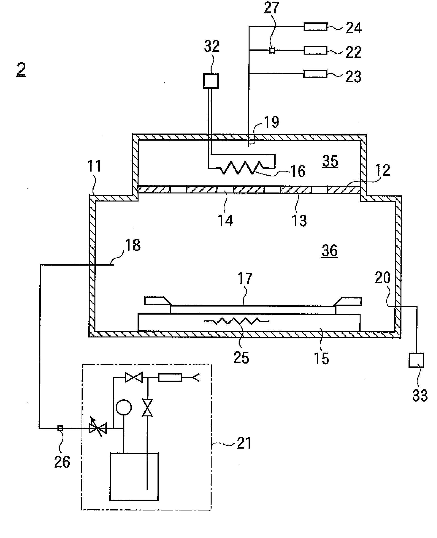
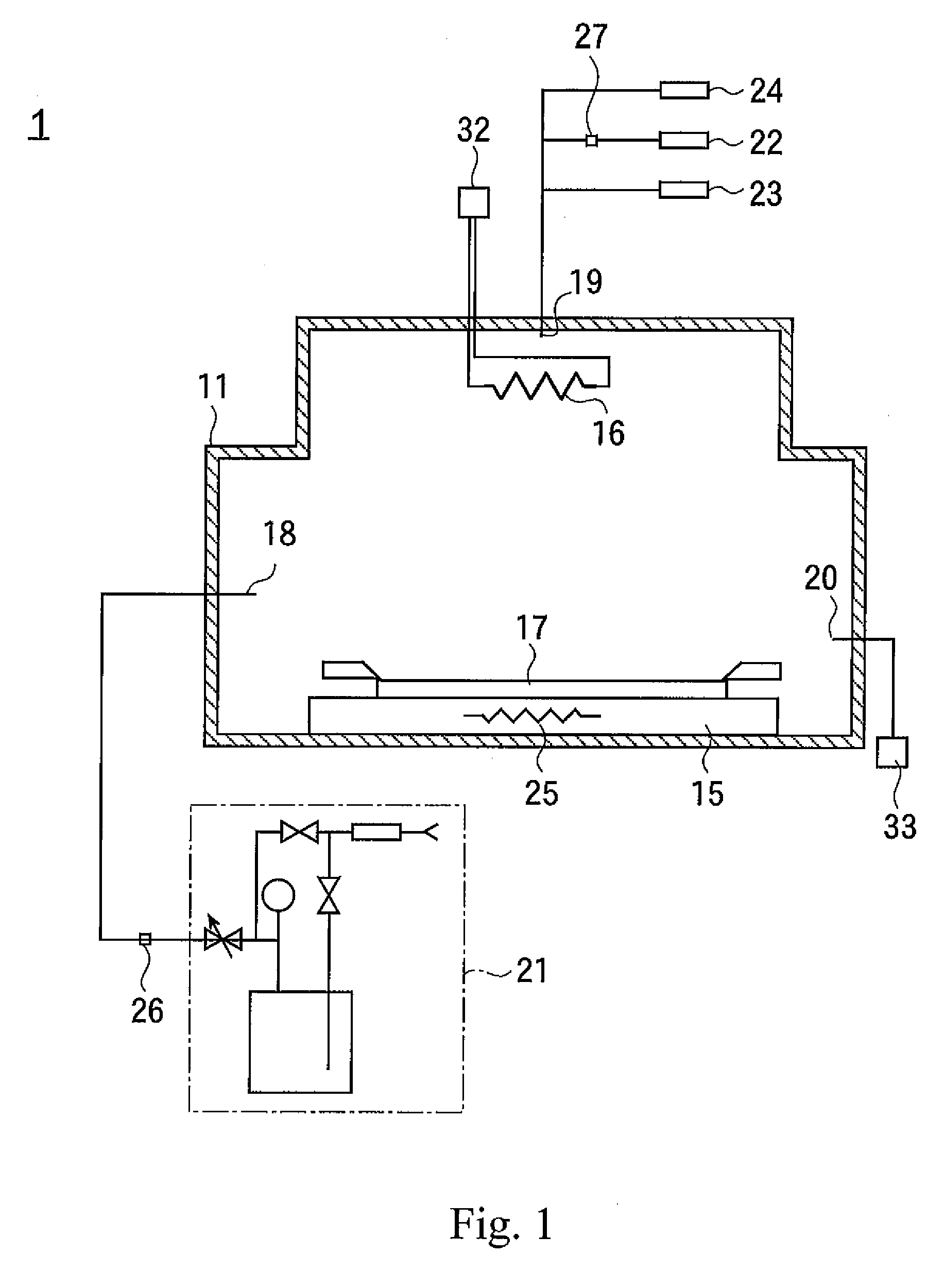
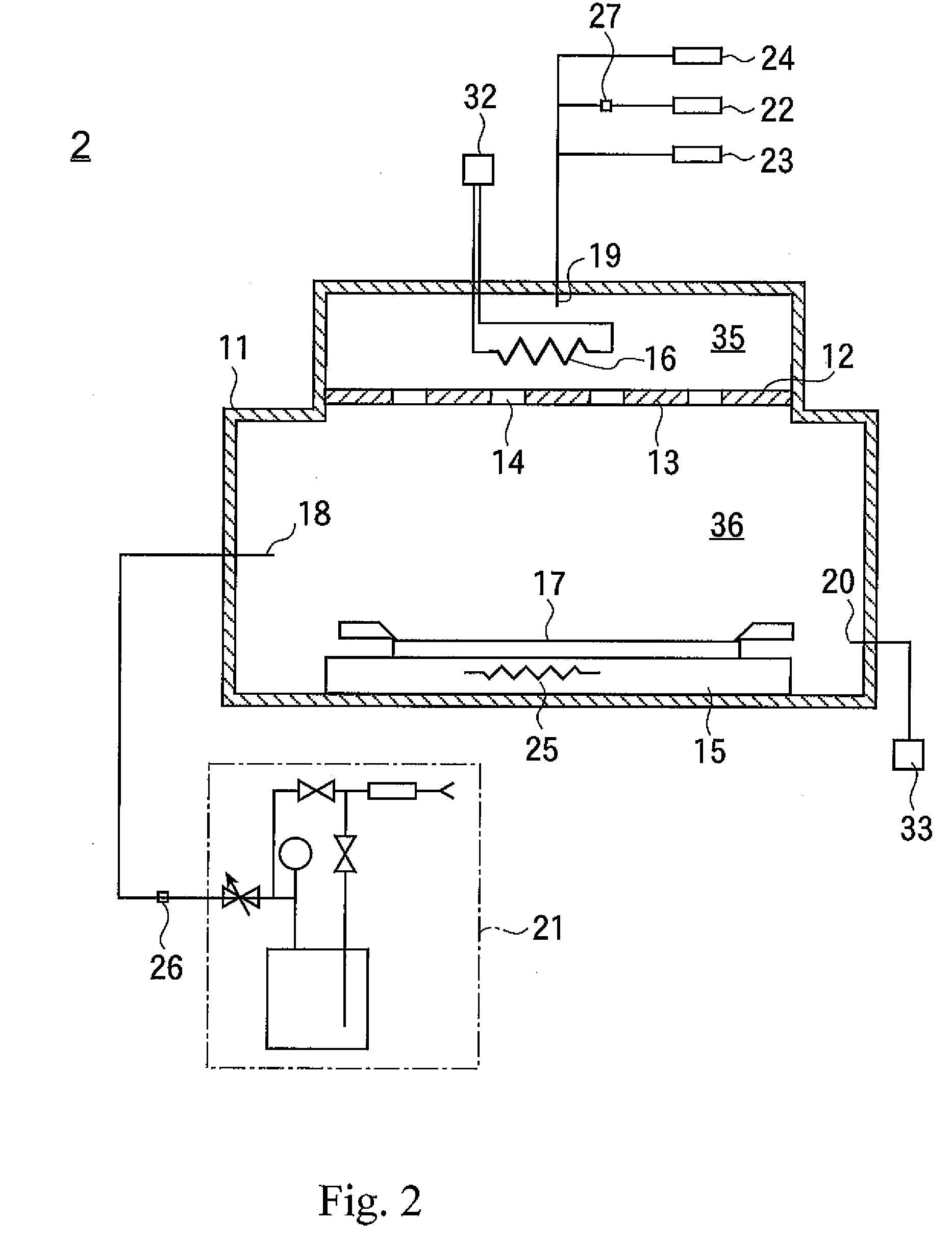
[0076]TiCl4 is used as a metallic material gas, NH3 is used as a reactive gas, H2 is used as an auxiliary gas, Ar is used as a back-flow preventing gas, and a TiN film is formed as a barrier film. Bubbling is done by blowing Ar into a TiCl4 source as a carrier gas, TiCl4 is introduced into a vacuum chamber 11 together with the carrier gas. A catalytic material 16 is a tungsten wire, and heated to a temperature of 1750 degrees Celsius.

[0077]When the auxiliary gas and the reactive gas are in contact with the catalytic material 16, highly reactive radicals are produced by a catalytic action.

[0078]H* and H2* are produced from H2, whereas NH*, NH2* and NH3* are produced from NH3 (* denotes a radical)

[0079]The flow rate of the metallic material gas is set at 50 sccm, the flow rate of the auxiliary gas is set at 200 sccm or zero, the flow rate of the reactive gas is changed, and the relationship between the specific resistance of an obtained barrier film (TiN film) and the flow rate of the...


PUM

PropertyMeasurementUnit
temperatureaaaaaaaaaa
temperaturesaaaaaaaaaa
chemical structureaaaaaaaaaa

Abstract

A film forming apparatus is used in a semiconductor manufacturing process and a method for producing a barrier film is used for a semiconductor. When a metallic gas and a reactive gas are alternatively flown, a back-flow preventing gas and an auxiliary gas are flown, the reactive gas and the auxiliary gas are moved with the flow of the back-flow preventing gas, and radicals are produced by being in contact with them to a catalytic material. Since the metallic material gas is not in contact with the catalytic material, the catalytic material is not degraded. A shower plate may be disposed between a radical producing chamber and a reaction chamber, so that the radicals are fed into the reaction chamber through holes. Thus, a barrier film having low resistance and excellent coverage is formed.

Description

[0001]The present invention is a Continuation of International Application No. PCT / JP2007 / 058311 filed Apr. 17, 2007, which claims priority to Japan Patent Document No. 2006-114789, filed on Apr. 18, 2006. The entire disclosures of the prior applications are hereby incorporated by reference herein in their entireties.BACKGROUND[0002]The present invention generally relates to a film forming apparatus for use in a semiconductor-producing process and a method for producing a barrier film to be used in a semiconductor.[0003]In the process for producing Cu wirings to be used in semiconductor devices, the film forming temperature is limited to 300 degree Celsius or less. This is the reason why when the film forming temperature is not less than 300 degrees Celsius, a phenomenon so-called stress migration (SM) occurs to the Cu wiring so that the reliability of the Cu wirings is conspicuously deteriorated.[0004]In a conventional art, a method is carried out in which an easily pyrolyzable MO-...

Claims


Application Information

Patent Timeline
Patent Type & Authority Applications(United States)
IPC IPC(8): C23C16/442
CPCC23C16/452C23C16/45519H01L21/76843H01L21/28556C23C16/45523C23C16/4401C23C16/45565
Inventor HARADA, MASAMICHI
Owner ULVAC INC
Learn More