Digital signal processing in optical systems used for ranging applications

a digital signal processing and optical system technology, applied in noise figure or signal-to-noise ratio measurement, distance measurement, instruments, etc., can solve the problems of relative simplicity of analog electronic design at the expense of performance and flexibility, output, and experienced users cannot always be aware of false range measurement events, etc., to achieve the effect of more efficien

Active Publication Date: 2009-05-07
LEDDARTECH INC
View PDF10 Cites 27 Cited by
  • Summary
  • Abstract
  • Description
  • Claims
  • Application Information

AI Technical Summary

Benefits of technology

[0014]It is therefore a first object of the present invention to provide a method for implementing more efficient digital processing of optical rangefinder data wherein the level of averaging of a set of received signal waveforms accounts for the range-dependent signal-to-noise characteristics of the instrument while providing response times suited to the range to the targeted object.
[0015]Another object of the present invention is to provide a method for digital processing of optical rangefinder data in which the SNR-enhancing capability of standard signal averaging techniques is maintained when ranging objects that move over significant distances during the acquisition of the return signal waveforms.
[0016]Yet another object of the present invention is to provide a method for digital processing of optical rangefinder data in which the SNR-enhancing capability of signal averaging techniques is maintained while allowing the measurement of the relative velocity of a targeted object along the line of sight of the rangefinder.

Problems solved by technology

Unfortunately, the relative simplicity of the analog electronic designs is obtained at the expense of performance and flexibility.
Despite these useful add-ons, most analog rangefinders limit their output to the raw display of the measured range value, without any further information about the specific temporal shape of the received signal waveforms.
As a consequence, even an experienced user cannot always be aware of false range measurement events caused by the presence of clutter along the line of sight of the device, by the pointing jitter of the device, or by adverse weather conditions that cause inadvertent ranging events at ranges closer than the aimed object.
The primary limitations of digital signal processing now come from the desired maximum response time of the instrument.
Unfortunately, the response time is generally established from a fixed value of the integration time, this latter value being generally determined by the need to successfully range objects located at the maximum distance to be covered by the instrument.
As a result, the implementation of a standard signal averaging process may lead to an instrument response that would be too slow for some applications where nearby objects must be detected and ranged very quickly.
In fact, the difficulty originates from the integration of a fixed number of raw signal waveforms, which does not really take advantage of the important variations of the SNR response of typical optical rangefinders as a function of the range to the object.
Unfortunately, these requirements can be difficult to satisfy in practical situations, so that the SNR improvement resulting from standard signal averaging may be disappointing.
This situation occurs for instance when using lidar systems for the detection and ranging of remote aerosols and molecules, whose optical return characteristics are unstable and evolve rapidly with time.
In many cases, the digital correlation is performed on a processed waveform obtained by previously averaging a set of raw signal waveforms, so that the difficulties discussed earlier about the standard signal averaging process still remain.

Method used


Image

  • Digital signal processing in optical systems used for ranging applications
  • Digital signal processing in optical systems used for ranging applications
  • Digital signal processing in optical systems used for ranging applications

Examples


Embodiment Construction

General Overview of a Digital Rangefinder

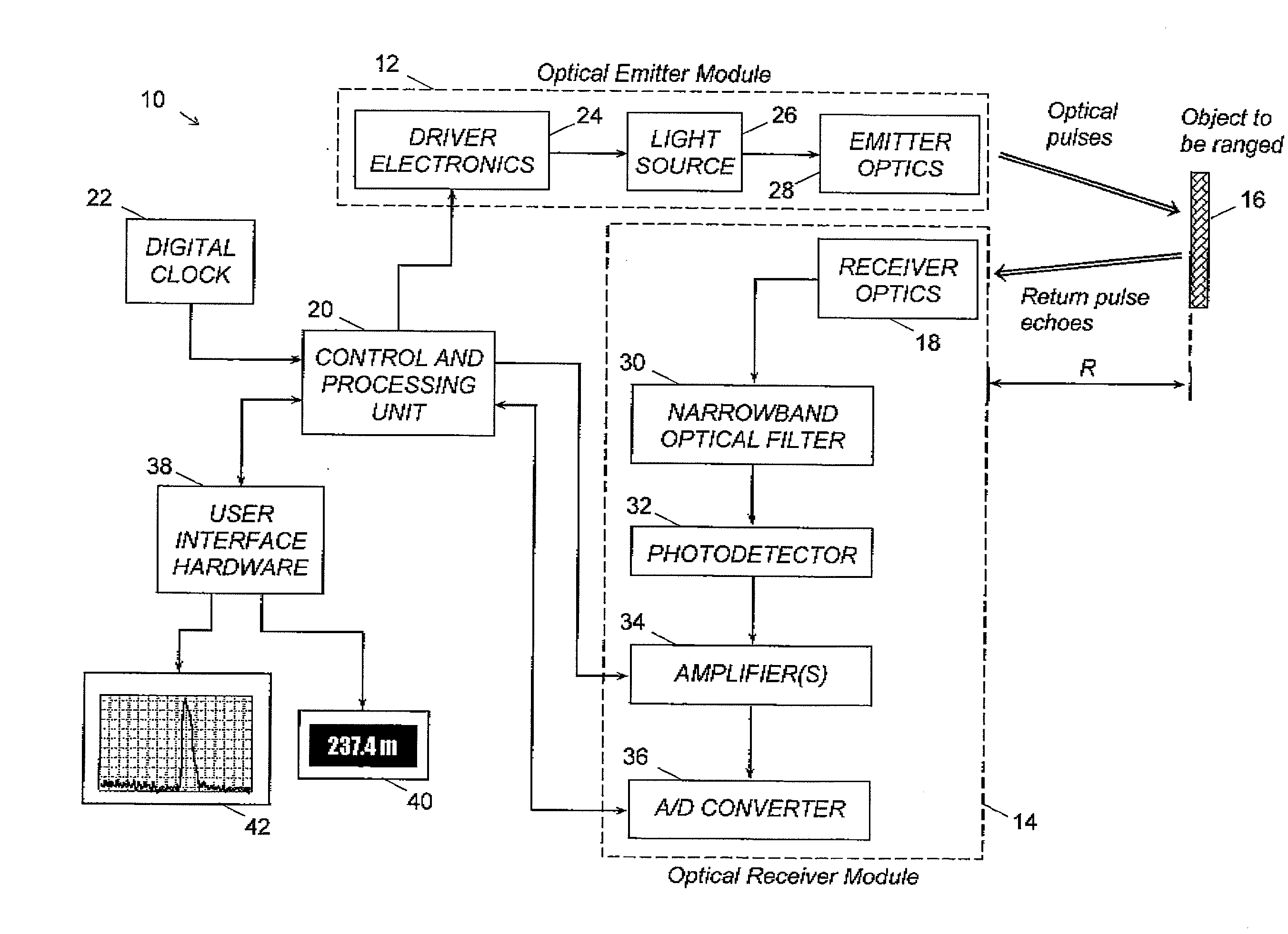
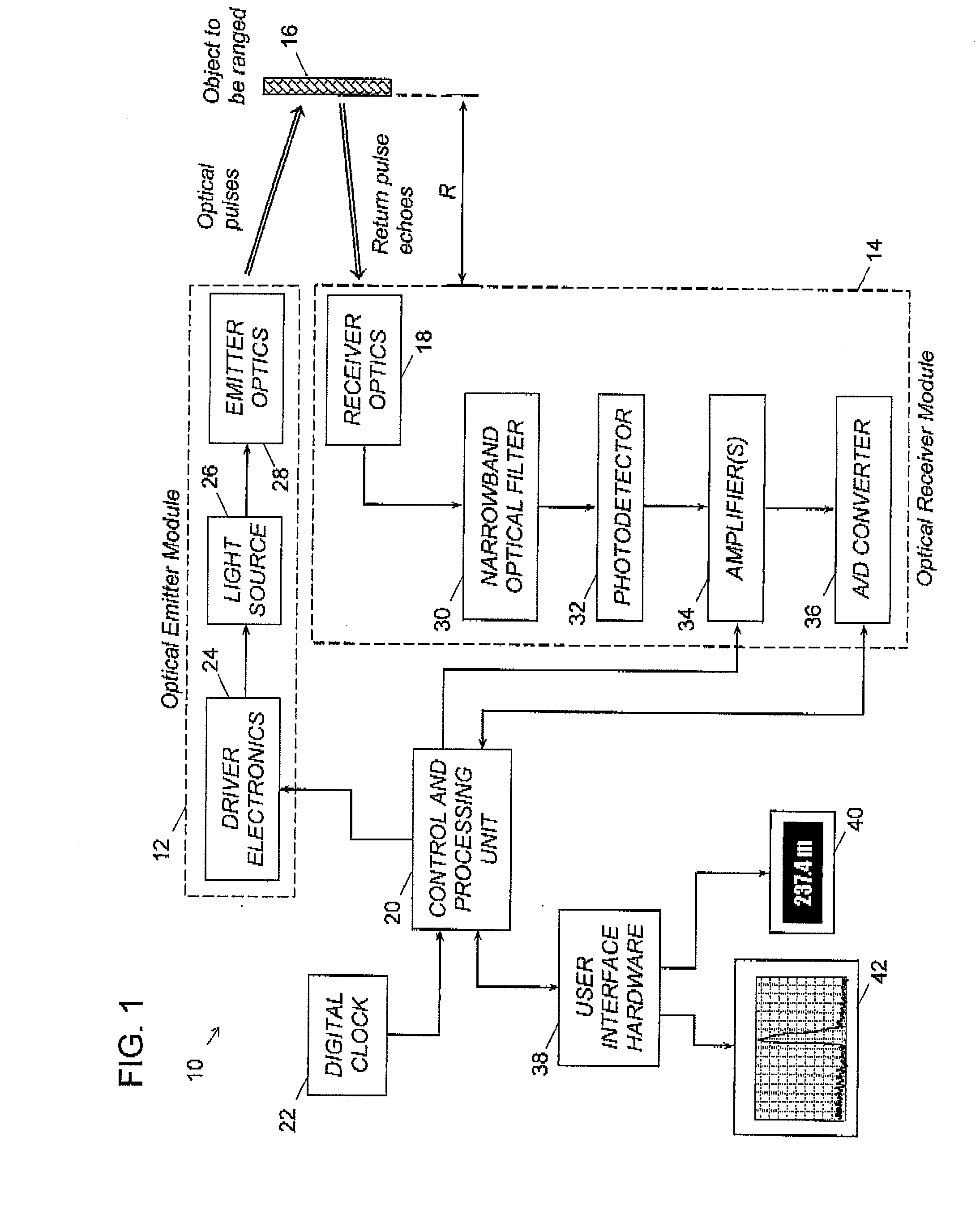
[0035]The various embodiments of the invention described below are intended for implementation in an optical rangefinding apparatus with digitization of the received signal waveforms. The basic elements of a digital rangefinder 10 can be better appreciated by referring to the schematic block diagram depicted in FIG. 1. The instrument comprises an optical emitter module 12 for emission of a train of optical pulses having predetermined characteristics, and an optical receiver module 14 for the capture and pre-processing of the return signal waveforms. The signal waveforms originate from the fraction of the emitted optical pulse energy that is reflected or backscattered by the object 16 located at range R from the rangefinder 10, and which is in the field of view of the receiver optics 18. A control and processing unit 20 controls the operation of both optical emitter 12 and optical receiver 14 modules. Among other things, the control process sy...


PUM


Abstract

Methods and apparatuses for reducing the response time along with increasing the probability of ranging of optical rangefinders that digitize the signal waveforms obtained from the pulse echoes returned from various types of objects to be ranged, the pulse echoes being too weak to allow successful ranging from a single waveform or the objects being possibly in motion during the capture of the pulse echoes. In a first embodiment of the invention, the response time at close range of a digital optical rangefinder is reduced by using a signal averaging process wherein the number of data to be averaged varies with the distance according to a predetermined function. In a second embodiment of the invention, the probability of ranging objects in motion along the line of sight of a digital optical rangefinder is increased and the object velocity measured by performing a range shift of each acquired signal waveform prior to averaging. In a third embodiment of the invention, the signal waveforms acquired in the line of sight of a digital optical rangefinder are scanned over a predetermined zone and range shifted and averaged to allow for early detection and ranging of objects that enter in the zone.

Description

FIELD OF THE INVENTION[0001]This invention generally relates to methods for improving the performance of an optical rangefinder used for measuring the distance to a moving object, and more particularly to methods for increasing the signal to noise ratio along with obtaining shorter response times for a time-of-flight rangefinder through digital processing of the received signal waveforms.DESCRIPTION OF THE PRIOR ARTLidar Systems[0002]Radiation with wavelength in the optical region of the electromagnetic spectrum i.e., from the ultraviolet up to the infrared, can interact with matter in various states through mechanisms such as optical absorption and scattering. Early after the advent of the first lasers, it was recognized that these novel sources of coherent optical radiation could be used for sensing solid objects, particulate matter, aerosols, and even molecular species located at long distances. Remote sensing applications emerged owing to some distinctive features of laser sourc...

Claims


Application Information

Patent Timeline
Patent Type & Authority Applications(United States)
IPC IPC(8): G06F19/00
CPCG01S7/484G01S17/10G01S7/487G01S7/4868
Inventor LEVESQUE, MARCBABIN, FRANCOISCANTIN, DANIEL
Owner LEDDARTECH INC
Why Eureka
Try Eureka