Method and Apparatus for Implementing Digital Logic Circuitry

a technology of logic circuits and logic logic, applied in the field of digital logic circuitry improvement, can solve the problems of poor computational performance of design data flow machines compared to other available parallel computing techniques, wrong matching of tokens, and failure to achieve commercial success of using data flow machines for computation, etc., and achieve rapid programming and vast increase the effect of use of fpgas

Inactive Publication Date: 2009-05-07
ZIQTAG SASAN FALLAHI
View PDF1 Cites 22 Cited by
  • Summary
  • Abstract
  • Description
  • Claims
  • Application Information

AI Technical Summary

Benefits of technology

[0096]The digital control parameters may control an Field Programmable Gate Array (FPGA) to implement the digital logic circuitry. The data flow machine may be generated from high-level source code specifications. An advantage of this is that the usefulness of FPGAs may be vastly increased, since many logic circuits for an FPGA may be easily created. This allows the FPGA to be used as a

Problems solved by technology

For various reasons, earlier attempts to design Data Flow Machines have produced poor results regarding computational performance compared to other available parallel computing techniques.
This may result in wrong matching of tokens when performing calculations after the recursion is finished.
The drawback is that no indefinite delays such as data-dependent recursion may exist in the construction.
Up till now, none o

Method used


Image

  • Method and Apparatus for Implementing Digital Logic Circuitry
  • Method and Apparatus for Implementing Digital Logic Circuitry
  • Method and Apparatus for Implementing Digital Logic Circuitry

Examples


Embodiment Construction

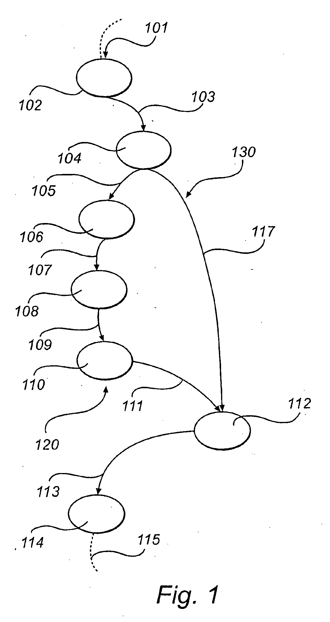
[0118]FIG. 1 illustrates an example of a part of a data flow graph comprising a plurality of nodes 102, 104, 106, 108, 110, 112, 114, each comprising at least one input and / or at least one output. The data flow between the nodes of the data flow graph is denoted by arcs 101, 103, 105, 107, 109, 111, 113, 115, 117. Each of said nodes 102, 104, 106, 108, 110, 112, 114 represent a logic operation performed on data present at the input of said nodes, respectively. The data present at the input of said nodes, normally referenced to as a token, can be considered to be held by said arcs, and the data held by said arcs are consequently the output of the nodes from which the arcs emanate, respectively. Regarding the example of FIG. 1, data on arc 101 is processed by node 102 and output to arc 103. The data on arc 103, which is present on the input of node 104, is processed by node 104, and the output from node 104 is output to arcs 105 and 117. Arc 117 is input to node 112, which cannot proc...


PUM


Abstract

A method of generating digital control parameters for implementing digital logic circuitry comprising functional nodes with at least one input or at least one output and connections indicating interconnections between said functional nodes, wherein said digital logic circuitry comprises a first path streamed by successive tokens, and a second path streamed by said tokens is disclosed. The method comprises determining a necessary relative throughput for data flow to said paths; assigning buffers to one of said paths to balance throughput of said paths; removing assigned buffers until said necessary relative throughput is obtained with minimized number of buffers; and generating digital control parameters for implementing said digital logic circuitry comprising said minimized number of buffers. An apparatus, a computer implemented digital logic circuitry, a Data Flow Machine, methods and computer program products are also disclosed.

Description

TECHNICAL FIELD[0001]The present invention relates to improvement of digital logic circuitry. In particular, the invention relates to balancing relative throughput of data flow paths diverging in a first node and converging in a second node, with a suitable use of hardware area resources. The invention relates to apparatuses, methods and computer program products for carrying out the improvements.BACKGROUND OF THE INVENTION[0002]Many different approaches towards easy-to-use programming languages for hardware descriptions have been employed in the recent years for providing a fast and easy way to design digital circuitry. When programming Data Flow Machines, a language different from the hardware descriptive language may be used. In principle, an algorithm description for performing a specific task on a Data Flow Machine only has to comprise the description itself, while an algorithm description which is to be executed directly in an integrated circuit must comprise many details of t...

Claims


Application Information

Patent Timeline
IPC IPC(8): G06F9/06
CPCG06F17/5054G06F9/4436G06F9/4494G06F30/34
Inventor MOHL, STEFANBORG, PONTUS
Owner ZIQTAG SASAN FALLAHI
Why Eureka
Try Eureka