Crawler for inspecting pipes

a crawler and pipe technology, applied in the direction of instruments, process and machine control, distance measurement, etc., can solve the problems of pipe loss, inability to visually inspect the pipe, injury to persons and the environment, etc., and achieve the effect of improving the scanning cycle tim

Inactive Publication Date: 2009-05-14
FABTEC SOLUTIONS
View PDF2 Cites 58 Cited by
  • Summary
  • Abstract
  • Description
  • Claims
  • Application Information

AI Technical Summary

Benefits of technology

[0008]The embodiments of the present invention solve the aforementioned problems by providing a system to automatically keep a crawler on the apex of a pipe. An inclinometer provides an electrical signal proportional to the angle at which the crawler is currently oriented on the pipe. This electrical signal is sent back to the Control Panel Unit where it is configured and fed through the control algorithm. The Control Software then returns a set of signals used to provide control for both the right and left motors. These control signals are then sent back to the Driver Unit where they are translated into their respective motor speeds. Driving one motor faster than the other will allow the crawler to respond by driving back up the pipe wall to correct the mechanical angle of the inclinometer, thus keeping the crawler on the apex of the pipe. Support brackets attached to the crawler allow for mounting of a radiation source, a radiation camera, and automated movement for obstacle clearance. Automated equipment may include electrical or pneumatic actuators used onboard to improve scanning cycle time.
[0009]An object of the embodiments of the present invention is to provide a vehicle for carrying a pipe inspection device on the apex of a pipe that is self-guiding and self-correcting.
[0010]An advantage of the embodiments of the present invention is that they have the ability to self-correct or navigate on various diameter pipes.

Problems solved by technology

The failure of these pipelines can cause not only a loss of the transported fluid but also injury to persons and the environment.
Unfortunately, the pipes cannot be visually inspected because the failures are due to internal damage and secondly pipelines usually have an insulating layer disposed on the pipe preventing any type of visual inspection.
These failures are caused by deterioration over time due to erosion or corrosion.
In addition, the vehicle must be easy to operate with minimal assistance and without highly qualified or technical support.
These systems have several obvious disadvantages, such as inserting the vehicle and gathering the data that is generated.
This system uses one or two motors to drive the vehicle on the pipe, but does not teach or imply any type of stabilization or steering system.
Without the use of outriggers, the crawler will bind or fall off the pipe, causing significant delays in inspections.
This methodology for stabilizing and controlling the crawler's movements, limits the functionality to only straight pipeline sections.
Any bends / corner sections of the pipeline cannot be tested.
Disassembly and reassembly significantly reduces the amount of productivity with regard to the total amount of time required to perform an inspection from start to finish.
The main disadvantage of current technology is the need for external supports to help guide the crawler down the pipeline.
Linear DC voltage supplies are very large and heavy, so it is required to carry the supply in a truck with the operator that is analyzing the corrosion data.
No adjustment on wheel angle was utilized for traction enhancement of driver wheels resulting in frequent slippage, which is detrimental to final scan quality.
Using extraneous equipment, the external supports, requires a significant amount of time to setup and provide no benefit to the actual corrosion data being analyzed.
This method requires more equipment than needed, a longer setup and break down time, and data measurements that are never oriented to a true vertical.
This setup also causes unbalanced wear on the system.
Drive wheel traction remains a problem in previous designs.
Because of this the current setup cannot function without the use of external guides, or outrigger supports.
Further, curved sections of pipe that were previously unable to be inspected can be checked giving a significant amount of inspection coverage that was not possible in the prior art.

Method used


Image

  • Crawler for inspecting pipes
  • Crawler for inspecting pipes
  • Crawler for inspecting pipes

Examples


Embodiment Construction

)

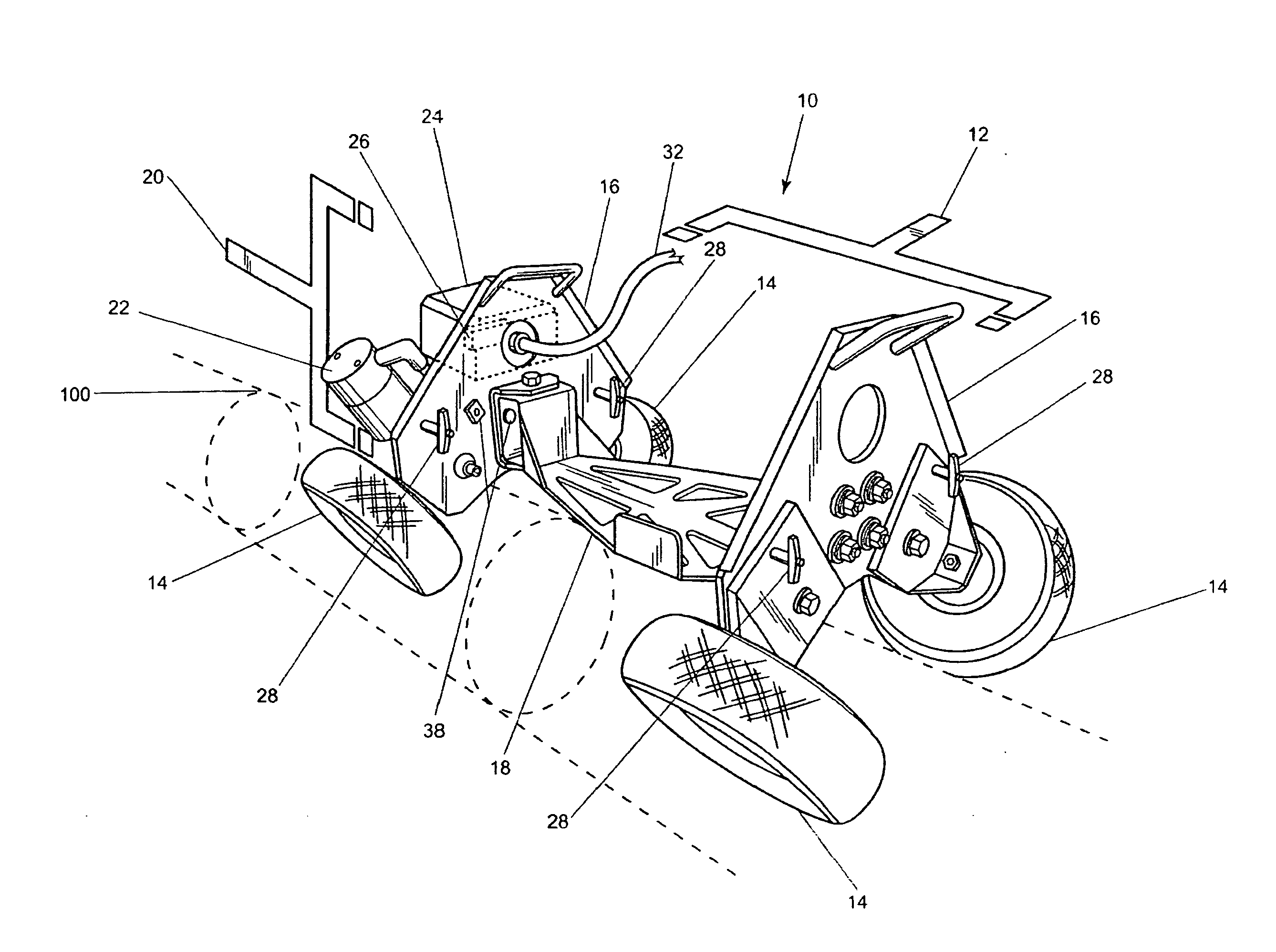
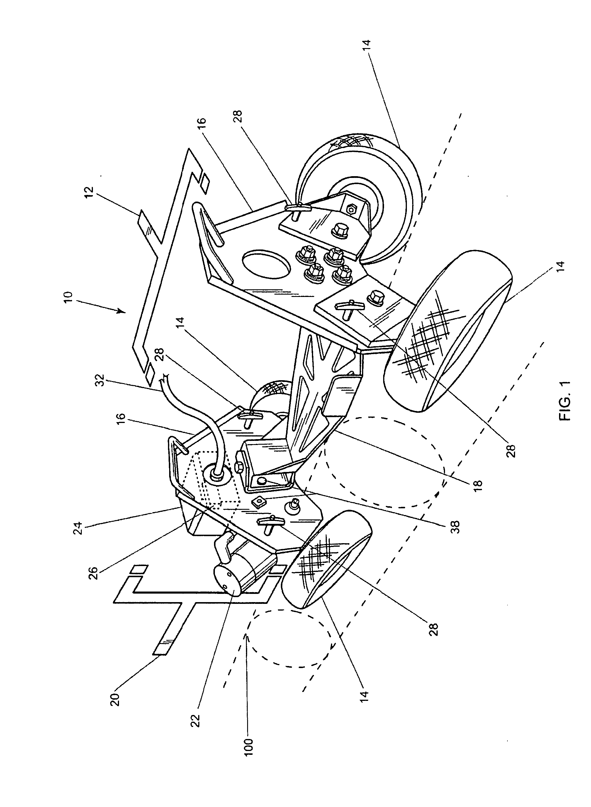
[0024]FIG. 1 shows a perspective view of the crawler. Crawler 10 has chassis 12 which rides on four (4) tires 14. Chassis 12 comprises end plates 16 and a frame 18 which make up the base of the crawler system. Tires 14 are preferably constructed for traction on a pipe surface 100. Tires 14 are solid tires with material removed 110, as shown in FIG. 5, by water jet, drilling, or other material removal to allow for damping and increase tire to pipe surface contact. Although solid tires are discussed, air or other fluid filled tires can be used with varying types and designs of tread patterns, with or without magnetic qualities, or in the alternative a track driving system could be employed (not shown). Crawler 10 further comprises drive system 20 which contains one or more drive motors 22 used for forward motion and steering. For the embodiment shown, two (2) drive motors 22 are shown independently driving front tires 14. However, this disclosure is intended to include a separate dri...


PUM


Abstract

Robotic external pipeline crawler system employs the use of logic control to provide a system capable of constantly and accurately maintaining a position at the vertex of the pipe. This apex positioning can be maintained as it traverses the length of the pipe being inspected. This system is adaptable to both straight and curved pipe, multiple pipe diameters, and will substantially reduce set up time and vertical pipeline support crossing time. The crawler system also employs an advanced bracketry system which allows quick disconnecting and auxiliary powered movement allowing for decreased cycle time across pipe supports. The unique tire interface allows for additional surface area contact making extreme environmental conditions possible.

Description

BACKGROUND OF THE INVENTION[0001]1. Field of the Invention (Technical Field)[0002]The embodiments of the present invention relate to pipe inspection and more particularly to a method and apparatus for using and controlling a crawler to inspect the integrity of installed pipes.[0003]2. Background Art[0004]Pipelines are used around the world to transport fluids for a multitude of applications including refineries and power plants. The failure of these pipelines can cause not only a loss of the transported fluid but also injury to persons and the environment. Thus, the integrity of the pipelines must be periodically checked to avoid failures. Unfortunately, the pipes cannot be visually inspected because the failures are due to internal damage and secondly pipelines usually have an insulating layer disposed on the pipe preventing any type of visual inspection. These failures are caused by deterioration over time due to erosion or corrosion. Various methods have been used to measure the ...

Claims


Application Information

Patent Timeline
Patent Type & Authority Applications(United States)
IPC IPC(8): G01M19/00G01M99/00
CPCF17D5/00G05D1/0891F17D3/08
Inventor JACOBSON, DWIGHT W.JACOBSON, JON D.JACOBSON, PAUL M.
Owner FABTEC SOLUTIONS
Why Eureka
Try Eureka