Although DLP-based projectors demonstrate capability to provide the necessary light
throughput,
contrast ratio, and color
gamut for most projection applications from desktop to large cinema, there are inherent resolution limitations, with current devices providing only 2148×1080 pixels.
In addition, high component and
system costs have limited the suitability of DLP designs for higher-quality digital cinema projection.
Moreover, the cost, size, weight, and complexity of the Philips or other suitable prisms as well as the fast
projection lens with a long working distance required for brightness are inherent constraints with negative
impact on acceptability and
usability of these devices.
However, LCD components have difficulty maintaining the high quality demands of digital cinema, particularly with regard to color and contrast, as the high
thermal load of high brightness projection affects the materials polarization qualities.
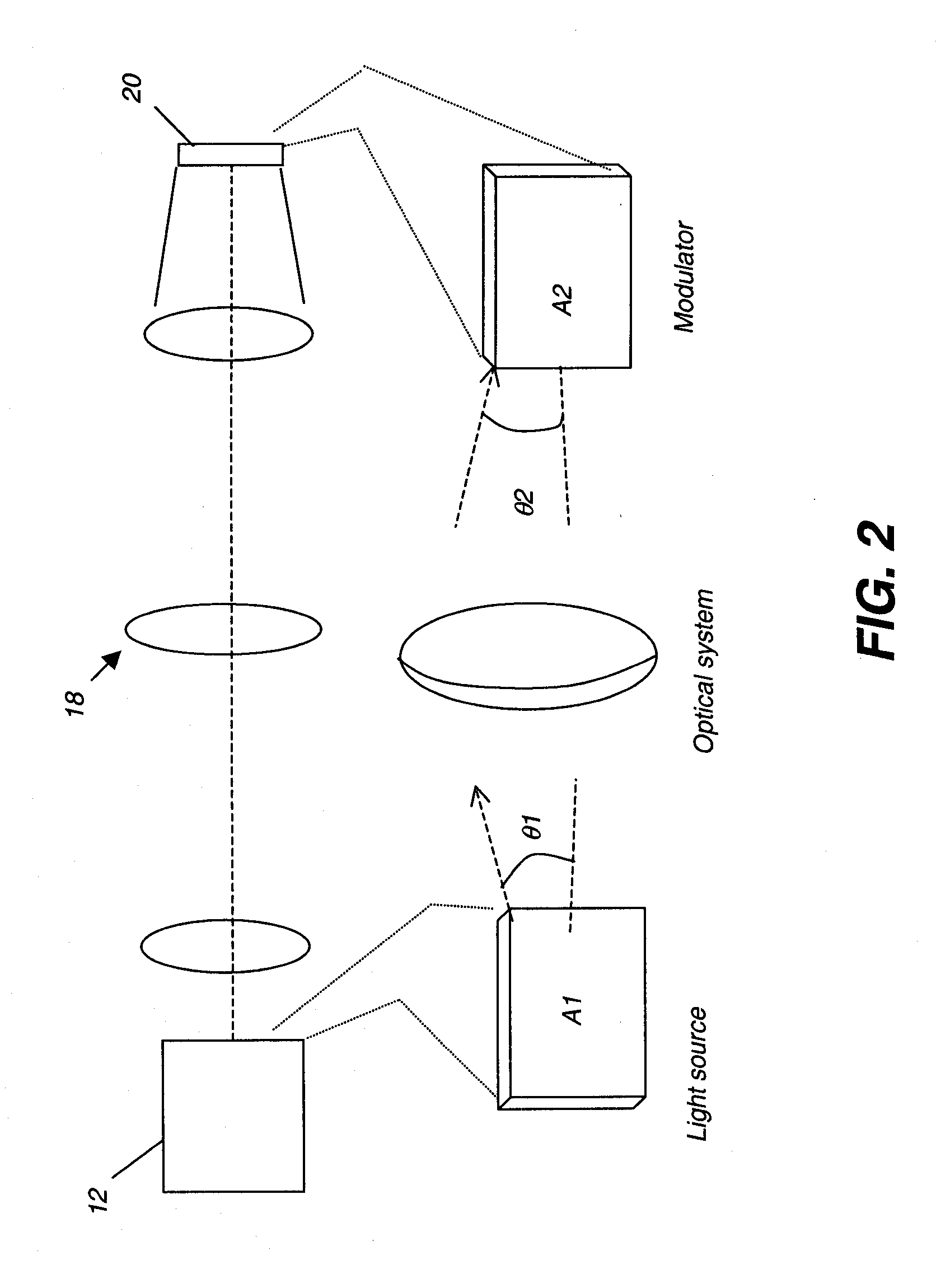
A continuing problem with illumination efficiency relates to etendue or, similarly, the Lagrange invariant.
Similarly, increasing the
source image size, so that light originates over a larger area, increases etendue.
Typically, however, the larger the image, the more costly and sizeable the
optics and support components.
This is especially true of devices such as LCOS and DLP components, where the
silicon substrate and defect potential increase with size.
As a general rule, increased etendue results in a more complex and costly optical design.
Moreover, although a configuration such as that disclosed in U.S. Pat. No. 5,907,437 handles light from three times the area of the final multicolor image formed, this configuration does not afford any benefit of increased brightness, since each color path contains only one-third of the total
light level.
Poorly matched etendue means that the optical
system is either light-starved, unable to provide sufficient light to the spatial light modulators, or inefficient, effectively discarding a substantial portion of the light that is generated for modulation.
LCD-based systems have been compromised by the requirement for polarized light, reducing efficiency and increasing etendue, even where polarization
recovery techniques are used.
DLP device designs, not requiring polarized light, have proven to be somewhat more efficient, but still require expensive, short lived lamps and costly optical engines, making them too expensive to compete against conventional cinema projection equipment.
Projection apparatus that meet these requirements typically cost in excess of $50,000 each and utilize high wattage
Xenon arc lamps that need replacement at intervals between 500-2000 hours, with typical replacement cost often exceeding $1000.
The large etendue of the
Xenon lamp has considerable
impact on cost and complexity, since it necessitates relatively fast
optics to collect and project light from these sources.
One drawback common to both DLP and LCOS LCD spatial light modulators (SLM) has been their limited ability to use
solid-state light sources, particularly laser sources.
Solid-state lasers promise improvements in etendue,
longevity, and overall spectral and brightness stability but, until recently, have not been able to deliver visible light at sufficient levels and within the cost needed to fit the requirements for digital cinema.
There are difficulties with each of these types of solutions.
In a high lumen
projector, however, this approach presents a number of difficulties.
Manufacturing yields drop as the number of devices increases and heat problems can be significant with larger scale arrays.
Coherence can also create problems for monolithic designs.
Coherence of the laser sources typically causes artifacts such as optical interference and speckle.
Additionally reducing the spatial and temporal coherence at the source is preferred, as most means of reducing this incoherence beyond the source utilizes components such as diffusers, which increase the effective extent of the source (etendue), cause additional light loss, and add expense to the
system.
However, conventional solutions using these devices are prone to a number of problems.
One limitation relates to device yields.
Due largely to heat and packaging problems for critical components, the commercialized VECSEL array is extended in length, but limited in height; typically, a VECSEL array has only two rows of emitting components.
The use of more than two rows tends to dramatically increase yield difficulties.
This practical limitation would make it difficult to provide a VECSEL illumination system for projection apparatus as described in the Glenn '145 disclosure, for example.
Although Kruschwitz et al '454 and others describe the use of laser arrays using organic VCSELs, these organic lasers have not yet been successfully commercialized.
In addition to these problems, conventional VECSEL designs are prone to difficulties with power connection and heat sinking.
Thus, there can be significant current requirements and
heat load from the unused current.
Coupling of the laser sources to the
projection system presents another difficulty that is not adequately addressed using conventional approaches.
However, these are more difficult to
package in array form and traditionally have a shorter lifetime at higher brightness levels.
None of the solutions yet proposed have addressed the problem of etendue-matching of the laser sources to the system, thermally separating the illumination sources from the optical engine.
Nor have these solutions adequately addressed the need to use polarized light from the laser devices more effectively.


