Electrochemical energy store

a technology of electrochemical energy and storage capacity, applied in secondary cells, electrochemical generators, battery servicing/maintenance, etc., can solve the problems of insufficient power yield of sulfur-lead accumulators, temperature dependence, and insufficient power yield of lithium ion accumulators, etc., to achieve the effect of improving the cold start capability and high operating temperatur

Active Publication Date: 2009-05-14
ROBERT BOSCH GMBH
View PDF5 Cites 37 Cited by
  • Summary
  • Abstract
  • Description
  • Claims
  • Application Information

AI Technical Summary

Benefits of technology

[0019]To compensate for temperature fluctuations, at times of standstill, the temperature may be lowered to a greater extent than the optimum required in the operation, in order better to absorb the heat, given off by cooling to the phase change material, in response to a renewed start-up of the electrochemical energy store or in response to driving off the vehicle in electrical operation, if the electrochemical energy store is used in a hybrid vehicle.
[0020]Furthermore, it is also possible to set the temperature of the electrochemical energy store higher by the tempering device and the heat exchanger at very low environmental temperatures, to prevent further cooling and thereby enable putting into operation of the electrochemical energy store at a higher operating temperature.
[0021]Moreover, it is also possible, at regularly low outside temperatures, to keep the temperature of the electrochemical energy store above the setpoint level, in order, in the case of fluctuations in the environmental temperature, especially in the case of further cooling, to reserve a safety range so as to make possible a secure operation of the electrochemical energy store. Correspondingly, at outside temperatures which are generally above the optimum operating temperature of the electrochemical energy store, it is also possible to set the setpoint temperature by the phase change material to a temperature that is below the optimum temperature, so as to be able better to compensate for a higher environmental temperature in this case too.
[0022]A further advantage of using the latent heat s

Problems solved by technology

However, the optimum power yield of lithium ion accumulators is temperature dependent.
In fact, the temperature range in which lithium ion accumulators are able to be operated effectively and with certainty is the range from −10° C. to 50° C. This temperature ran

Method used


Image

  • Electrochemical energy store
  • Electrochemical energy store
  • Electrochemical energy store

Examples


Embodiment Construction

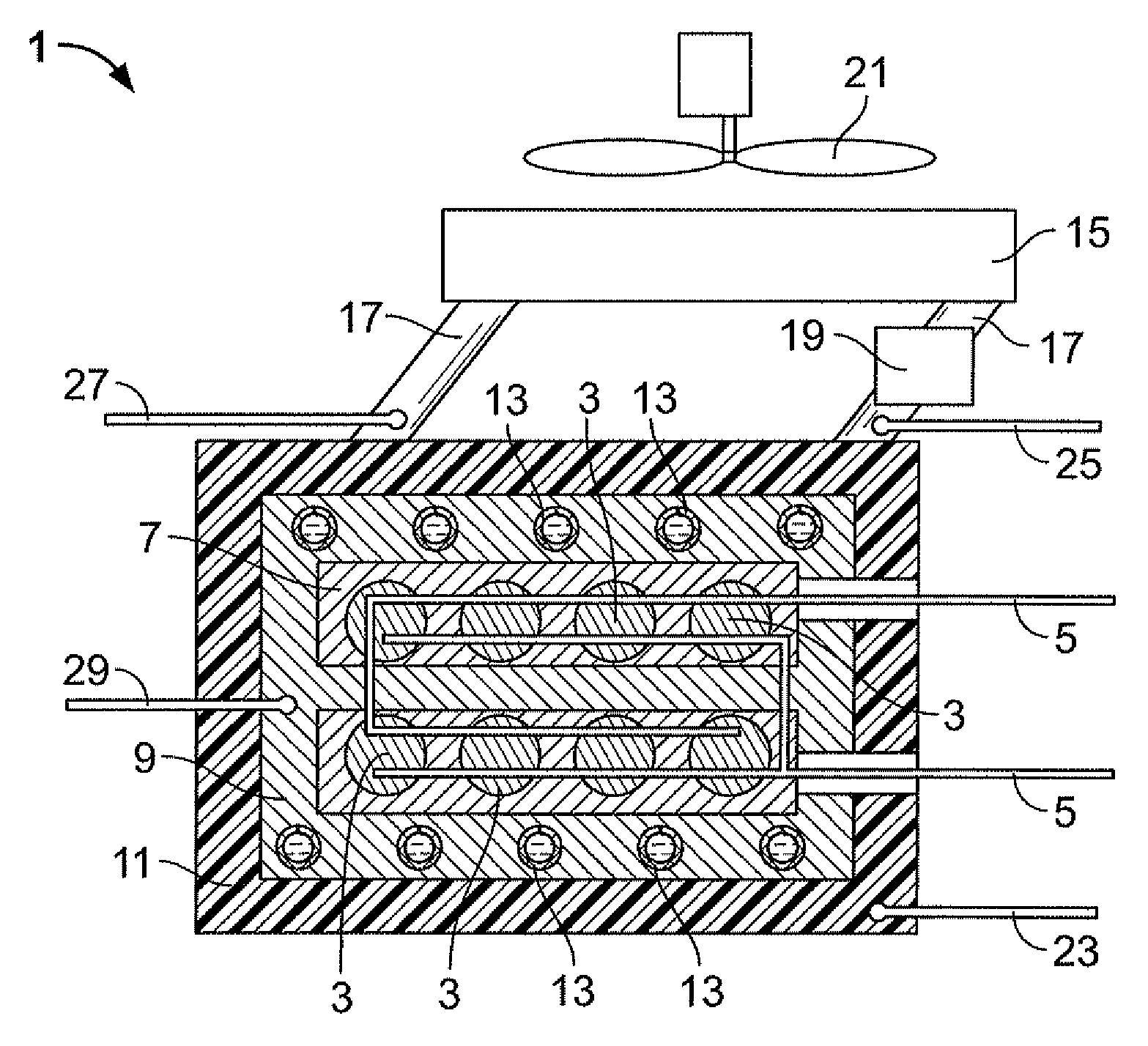
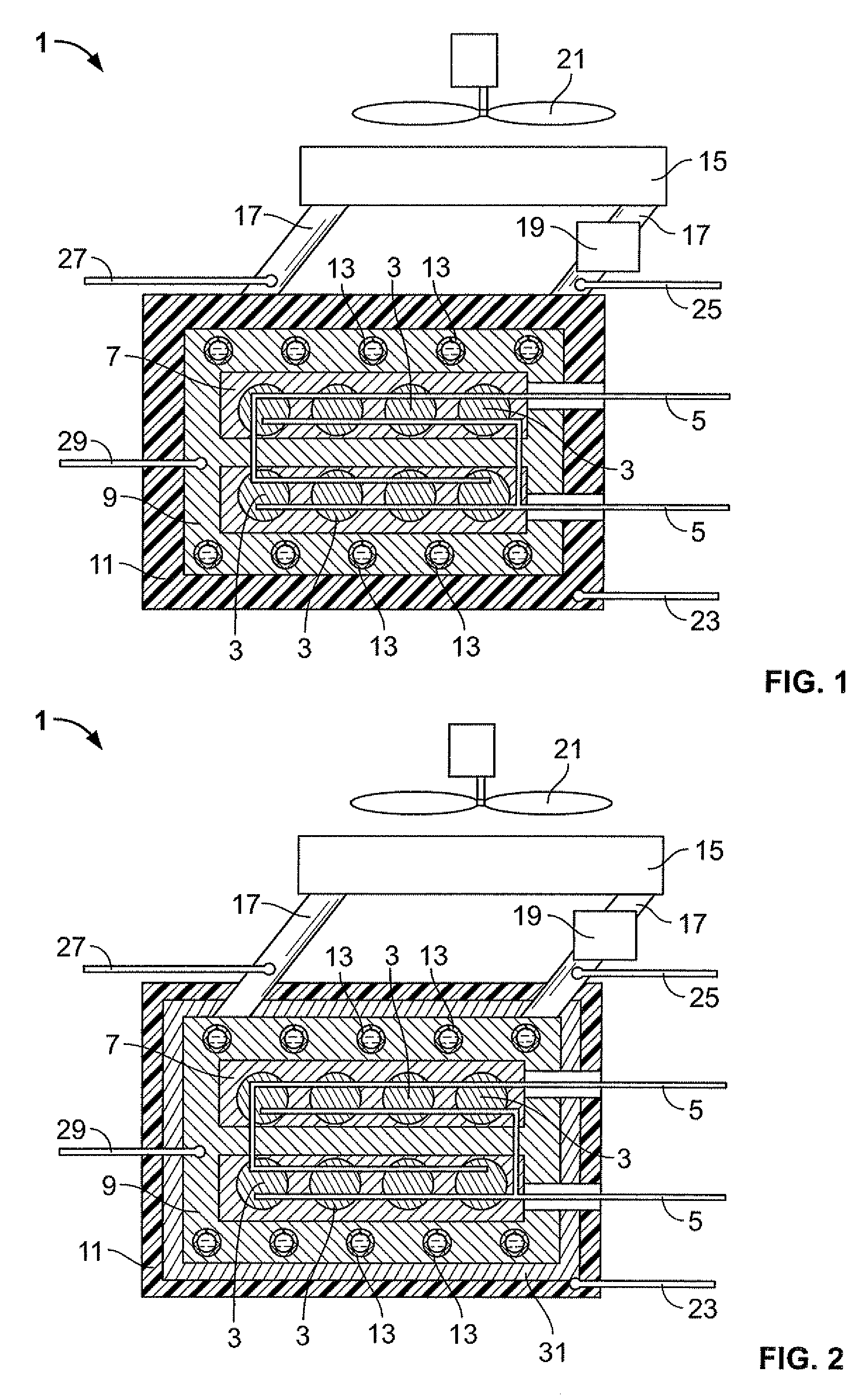
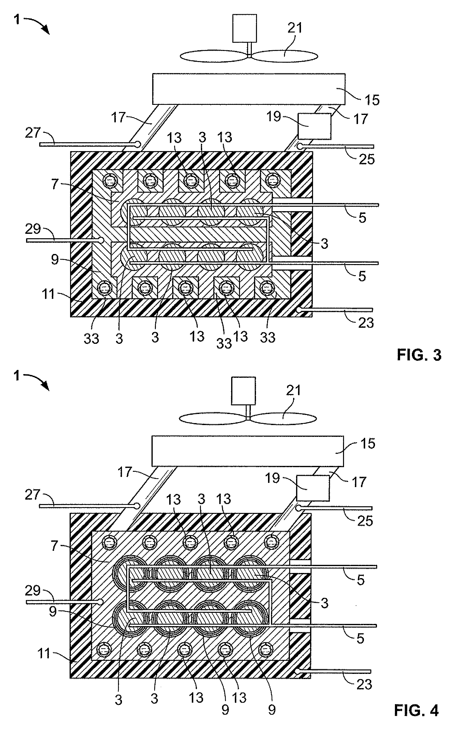
[0035]An electrochemical energy store 1 includes a plurality of electrochemical cells 3. The electrochemical cells are lithium ion accumulators, according to the exemplary embodiments and / or exemplary methods of the present invention. The individual electrochemical cells 3 each have an electric positive pole and an electric negative pole. The individual positive poles and the individual negative poles of electrochemical cells 3 are connected to one another via a current diverter 5. An electric consumer may be connected to current diverter 5.

[0036]Electrochemical cells 3 are enclosed by a heat conducting material 7. In turn, heat conducting material 7 is surrounded by a latent heat storage unit 9. Latent heat storage unit 9 includes a phase change material. Heat may be conducted from latent heat storage unit 9 to electrochemical cells 3 by heat conducting material 7. In the same way, electrochemical cells 3 are able to give off heat to latent heat storage unit 9 through heat conducti...


PUM


Abstract

An electrochemical energy store, including at least one electrochemical cell as well as at least one latent heat storage unit, which includes at least one phase change material. The at least one electrochemical cell is a lithium ion accumulator. The exemplary embodiments and/or exemplary methods of the present invention also includes the use of the electrochemical energy store in an electric vehicle or a hybrid vehicle. Furthermore, the exemplary embodiments and/or exemplary methods of the present invention relates to a method for temperature regulation of an electrochemical energy store.

Description

FIELD OF THE INVENTION[0001]The present invention relates to an electrochemical energy store. The present invention also relates to the use of the electrochemical energy store, as well as a method for the temperature regulation of the electrochemical energy store.BACKGROUND INFORMATION[0002]The development of hybrid vehicles and electric vehicles requires the application of efficient electrochemical energy stores. A sufficient performance is provided, for example, by lithium ion accumulators. However, the optimum power yield of lithium ion accumulators is temperature dependent. In fact, the temperature range in which lithium ion accumulators are able to be operated effectively and with certainty is the range from −10° C. to 50° C. This temperature range, however, is not sufficient for operation in a motor vehicle. Thus, it is also particularly desirable that a motor vehicle is also able to be operated in wintertime, when temperatures fall below −10° C. Temperatures of more than 50° ...

Claims


Application Information

Patent Timeline
IPC IPC(8): H01M10/24H01M10/50
CPCH01M10/0525H01M10/5004H01M10/5016H01M10/503Y02T10/7011H01M10/5077H01M10/5089H01M2200/10H01M10/5053H01M10/625H01M10/6568H01M10/643H01M10/6554H01M10/613H01M10/659Y02E60/10
Inventor ALKEMADE, ULRICHBAUMANN, FRANKWAHL, FLORIANSCHUMANN, BERND
Owner ROBERT BOSCH GMBH
Why Eureka
Try Eureka