
Method of detoxification treatment for filter with persistent substance adhering thereto

Inactive Publication Date: 2009-05-14
IDEMITSU KOSAN CO LTD
View PDF1 Cites 0 Cited by
  • Summary
  • Abstract
  • Description
  • Claims
  • Application Information

AI Technical Summary

Benefits of technology

[0036]The inventors made extensive studies to attain the above object, and has found that, by bringing a filter used in the treatment of hardly-decomposable-substance-containing water into contact with a peroxide for oxidation-decomposition of the hardly-decomposable-substance, the concentration of the hardly decomposable substance adhering to the filter can be decreased to a level sufficiently lower than the emission standard value without desorbing the hardly decomposable substance from the filter, and the filter can be discarded safely. The invention has been made based on this finding.
[0038]According to the invention, a filter used in a treatment system of hardly-decomposable-substance-containing water and having a hardly decomposable substance adhering thereto can be detoxified on site and discarded safely.
[0039]In particular, by combining the invention with the aforementioned cycle method for treating hardly-decomposable-substance-containing water proposed by the applicants, all of the hardly decomposable substances can be detoxified on site without the need of transportation or the like of the hardly decomposable substance which causes environmental pollution.

Problems solved by technology

However, these separating and removing techniques are not preferable since they are not only inefficient but also require a great deal of equipment investment since a diluted liquid is directly treated.
Further, when discharged water is badly contaminated, there may be some unfavorable cases where the emission standard value cannot be fulfilled even though the above techniques have been applied.
In this case, however, activated carbon that has once adsorbed a hardly decomposable substance still holds the hardly decomposable substance internally, and therefore, it cannot be discarded as it is.
However, this method involves the risk that an adsorbate may be discharged together with a discharged gas to cause secondary pollution, or may seep out from the land where it is filled to cause re-contamination.
Therefore, while some methods can be easily applied, others cannot be easily applied, depending upon the state of existence of a hardly decomposable substance.
For example, thermal decomposition or decomposition using supercritical water requires expensive facilities or energy, and there are many cases where they cannot be put into practice from an economical viewpoint.
Further, a method using a combination of ozone or hydrogen peroxide with ultraviolet light cannot be applied to a suspension that does not easily transmit ultraviolet light or a solid such as soil or sludge.
In general, harmful substances such as an endocrine-disrupting chemical cause a problem that, as operation becomes complicated, possibility of re-contaminating a human body or an ambient environment will increase.
As is understood from the above, conventional decomposition and removal treatments required a great deal of labor and a large amount of materials.
In the case of an ultraviolet irradiation treatment, for example, there is the problem that it can be applied only to a reaction system which transmits ultraviolet light and cannot be applied to a solid-containing liquid or a solid.
However, when a hardly decomposable organic compound is chemically decomposed by adding persulfate to such a hardly decomposable organic compound as disclosed in the above-mentioned Patent Document 1 or Patent Document 2, the decomposition efficiency of the hardly decomposable organic compound is low.
Therefore, it is extremely difficult to decompose the compound when it is contained at a high concentration.
However, such a metal salt is very expensive, and the use thereof is not practical from an economical viewpoint.
If a technique as disclosed in Patent Document 3 is applied to discharged water containing a small amount of a solid in a decomposed substance, a layer of a settled solid is not formed on a metal mesh, and a dioxin-containing solid of fine particles of a decomposed substance or dissolved dioxin pass through the metal mesh, and as a result, the treatment is sometimes insufficient.
This bisulfite or the like inhibits the chemical decomposition, and hence, it is hard to assert that such a technique is efficient for separation and removal of a hardly decomposable substance.

Method used


Image

  • Method of detoxification treatment for filter with persistent substance adhering thereto
  • Method of detoxification treatment for filter with persistent substance adhering thereto
  • Method of detoxification treatment for filter with persistent substance adhering thereto

Examples


example 1

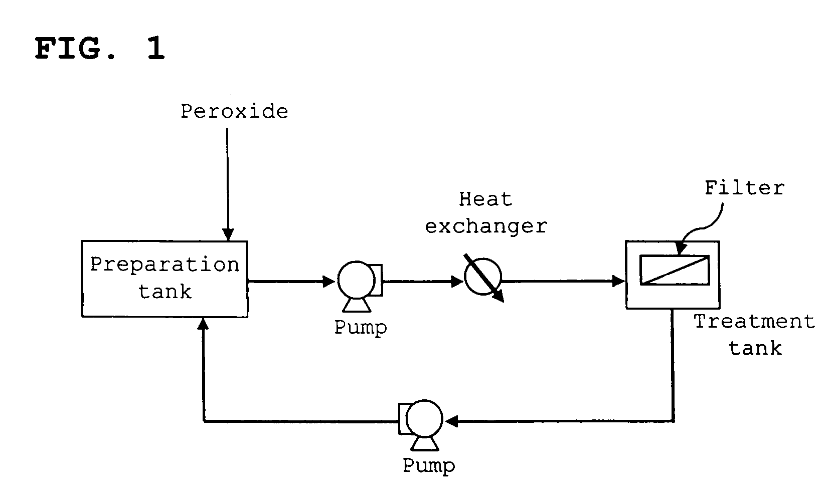
FIG. 1

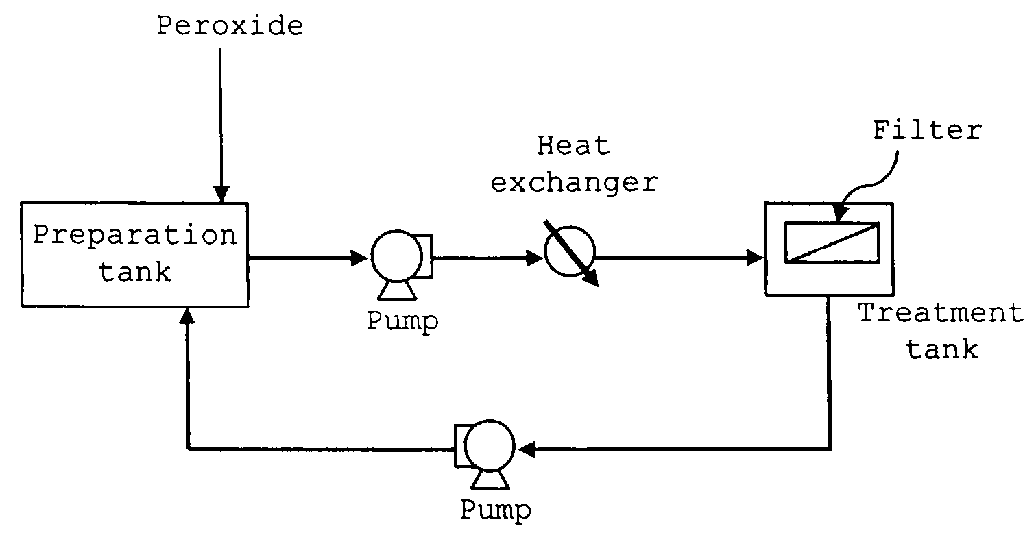
[0104]A microfiltration membrane (MF membrane) with dioxins adhering thereto was detoxified using the treatment apparatus shown in FIG. 1.

[0105]A hot water bath (volume: 1 L) (heat exchanger) heated to 95° C. was provided between a preparation tank (volume: 2 L) and a treatment tank (volume: 0.5 L). The preparation tank was connected to the treatment tank, through a hot water bath, with a Teflon (registered trademark) tube with a diameter of 0.5 cm. The lower part of the treatment tank was also connected to the preparation tank with a Teflon (registered trademark) tube. A tube pump was provided between the preparation tank and the hot water bath, and between the treatment tank and the preparation tank to allow a downwardly flowing stream to be generated in the treatment tank, as well as to allow the liquid to circulate.

[0106]A microfiltration membrane (MF membrane) with a diameter of 11 cm and a pore size of 0.45 μm contaminated with dioxins (dioxin concentration: 6500 pg-TEQ / ...

example 2

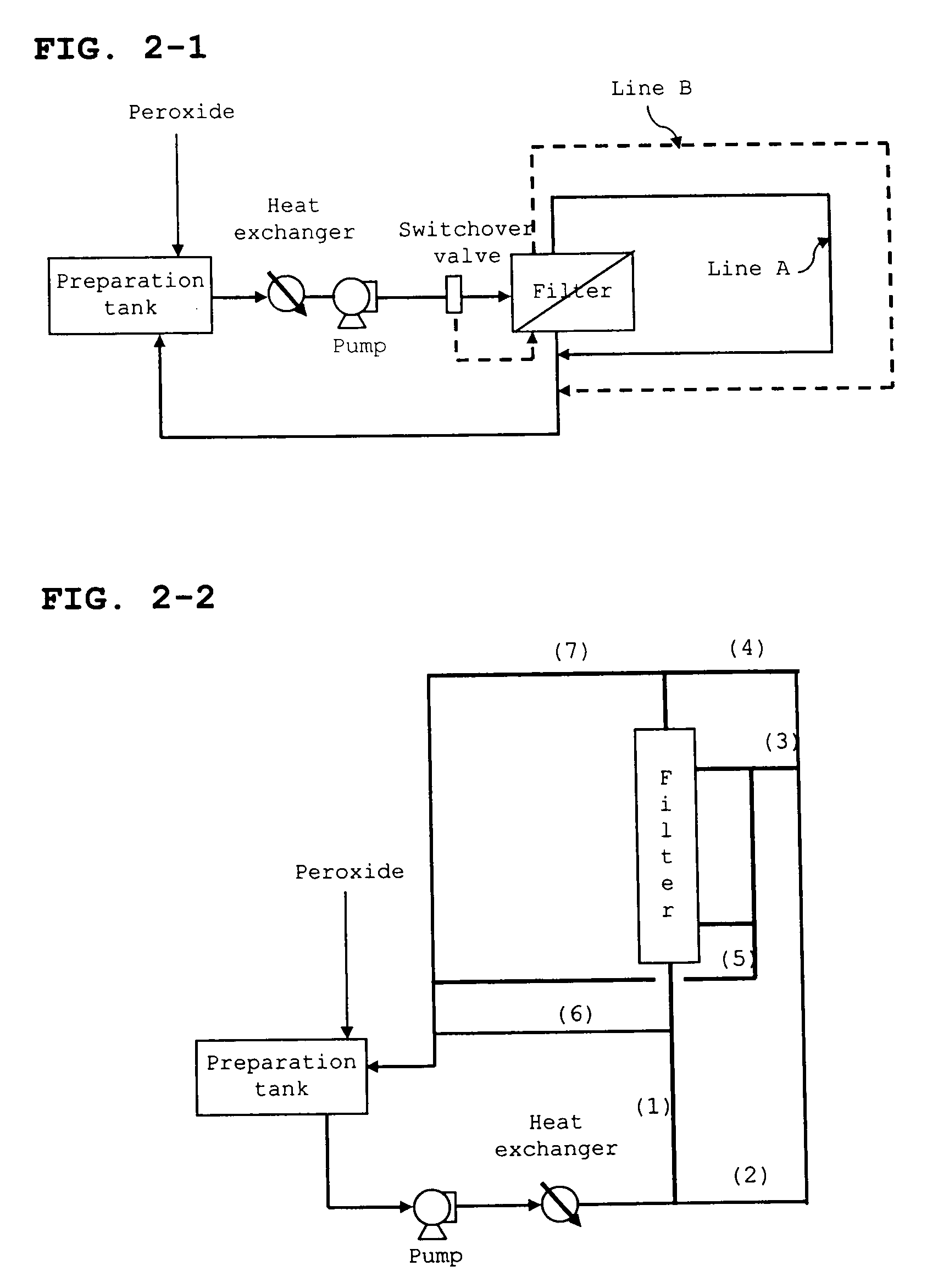
[0108]Using the treatment apparatus shown in FIG. 2-1, a pleated type filter with dioxins adhering thereto was detoxified.

[0109]A heat exchanger and a pump were provided between a preparation tank (10 L) and a filter contaminated with dioxins (dioxin concentration: 10000 pg-TEQ / g, pleated type, pore diameter: 2 μm, membrane area: 0.15 m2). A switchover valve was provided between the ejection port of the pump and the filter, whereby line A (a line which is normally used) running from the inlet of the filter to the outlet of the filter, and line B running from the outlet of the filter to the inlet of the filter were provided. As a result, the flow direction of the aqueous persulfate solution (chemicals) could be changed reversibly.

[0110]Sodium persulfate was successively added to the preparation tank every 24 hours in such a manner that the concentration of sodium persulfate became 3% within 2 hours. The liquid temperature was kept at 80° C., and the flow direction of the aqueous sodi...

example 3

[0112]Using the treatment apparatus shown in FIG. 2-2, a hollow fiber type filter with dioxins adhering thereto was detoxified.

[0113]A heat exchanger and a pump were provided between a preparation tank (100 L) and a filter contaminated with dioxins (dioxin concentration: 8000 pg-TEQ / g, hollow fiber type, cartridge Φ 16.5 cm, length 106.6 cm). Lines (1) to (7) were provided around the filter, and a valve was provided at a branch of each line. Combination of opening and closure of the valves was as follows.

1. The valves of lines (1), (5) and (7) are open with the valves of lines (2), (3), (4) and (6) being closed

2. The valves of lines (2), (4), (5) and (6) are open with the valves of lines (1), (3) and (7) being closed

3. The valves of lines (2), (3), (6) and (7) are open with the valves of lines (1), (4) and (5) being closed

[0114]The flow channel and liquid flow in 1 above are shown in FIG. 4-1, the flow channel and liquid flow in 2 above are shown in FIG. 4-2, and the flow channel an...


PUM


Abstract

A method for detoxifying a filter including the step of subjecting a filter with a hardly decomposable substance adhering thereto to chemical decomposition without desorbing the hardly decomposable substance from the filter.

Description

TECHNICAL FIELD[0001]The invention relates to a method for detoxifying a filter with a hardly decomposable substance adhering thereto which is used in treating water containing a hardly decomposable substance such as dioxins and other endocrine-disrupting substances.BACKGROUND[0002]In Japan, a law concerning special measures against dioxins was enacted in 1999, which regulates the emission standard value of dioxins to 10 pg-TEQ / L or less. However, discharged water caused by the demolition of incinerators, discharged water from particular industrial institutions, or part of water seeping from soil may contain dioxins at a concentration larger than the regulated amount. Therefore, development of a technology for reducing or removing dioxins is strongly desired.[0003]Other than dioxins, endocrine-disrupting substances (the so-called environmental endocrine disrupters or endocrine-disrupting chemicals) such as bisphenols, and various organic chlorine compounds represented by trichloroet...

Claims


Application Information

Patent Timeline
IPC IPC(8): B09B3/00A62D3/38B01D65/02
CPCB01D65/02B08B3/08B01D2321/28B01D2321/168A62D3/00B09B3/00
Inventor MURAMOTO, TAKAHISAMORIMITSU, KOZOMACHIDA, MASASHIYOSHIOKA, YOSHIYUKI
Owner IDEMITSU KOSAN CO LTD
Learn More