Methods for making optical fiber preforms and microstructured optical fibers

Inactive Publication Date: 2009-05-21
CORNING INC
View PDF10 Cites 30 Cited by
  • Summary
  • Abstract
  • Description
  • Claims
  • Application Information

AI Technical Summary

Benefits of technology

[0006]One aspect of the present invention relates to a method of making an optical fiber preform comprising gaseous voids. The optical fiber preform may be used to manufacture microstructured optical fibers. The method may comprise depositing layers of porous silica glass based soot inside a substrate tube by a modified chemical vapor deposition process. The silica glass based soot may then be consolidated in the s

Problems solved by technology

There are several disadvantages to the stack and draw method.
The awkwardness of assembling hundreds of very thin canes (defined by rods or tubes), as well as the possible presence of interstitial cavities when stacking and drawing cylindrical canes, may affect dramatically

Method used


Image

  • Methods for making optical fiber preforms and microstructured optical fibers
  • Methods for making optical fiber preforms and microstructured optical fibers
  • Methods for making optical fiber preforms and microstructured optical fibers

Examples


Embodiment Construction

[0015]The methods of the present invention utilize modified chemical vapor deposition (MCVD) techniques to form optical fiber preforms having a non-periodic distribution of gaseous voids. The resultant preform is used to produce a microstructured optical fiber. The microstructured optical fiber has a non-periodic distribution of voids formed from the gaseous voids in the preform.

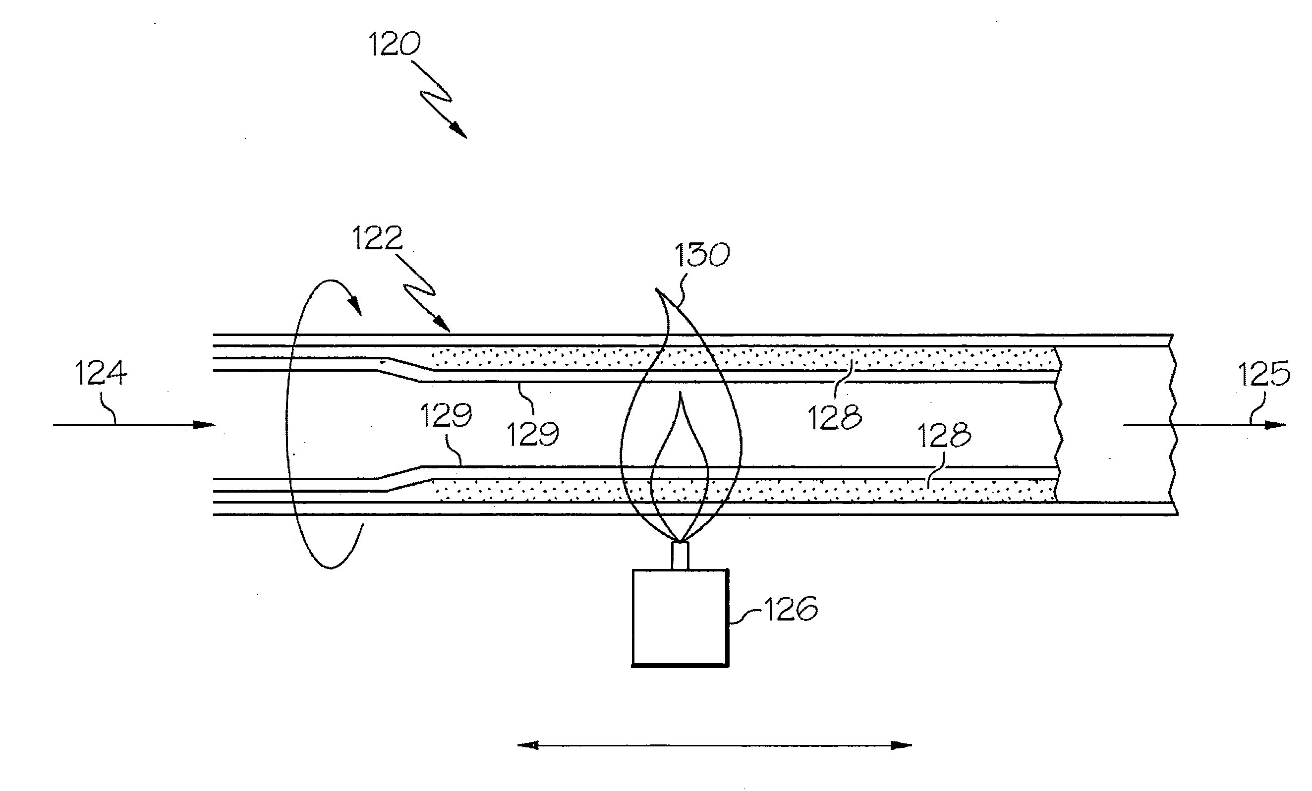
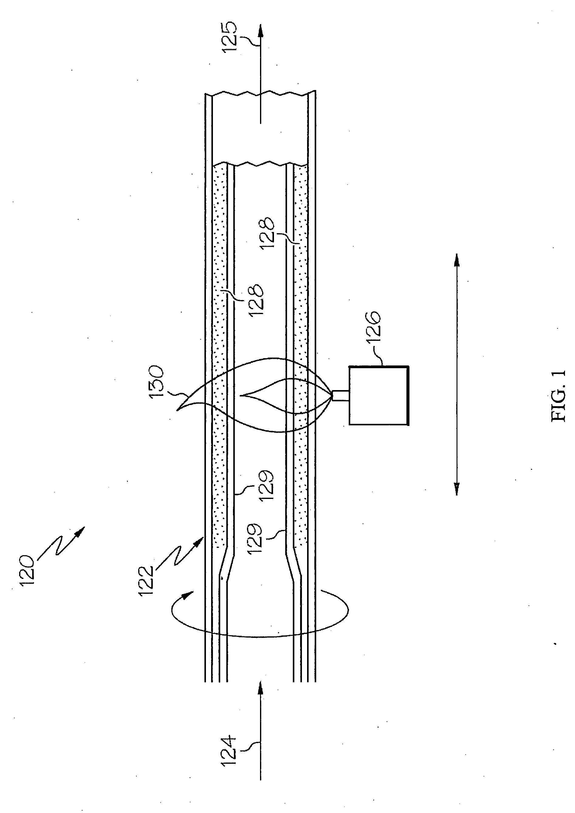
[0016]FIG. 1 is a schematic diagram of a MCVD operation 120 for making an optical fiber preform in accordance with the present invention. As shown in FIG. 1, a substrate tube 122 is positioned relative to a heat source. The heat source may comprise, without limitation, a burner, an electric resistance heater, an inductance heater, or an outside plasma torch. In the embodiment shown in FIG. 2 the heat source is a burner 126. Fuel, such as methane (CH4), and combustion supporting gas, such as oxygen, are supplied to the burner 126 and ignited to form the flame 130. Alternatively, the fuel supplied to the burne...


PUM

PropertyMeasurementUnit
Thicknessaaaaaaaaaa
Thicknessaaaaaaaaaa
Thicknessaaaaaaaaaa

Abstract

A method of making an optical fiber preform includes depositing silica glass soot on the inside of a substrate tube via a chemical vapor deposition operation. The silica glass soot is consolidated into silica glass under controlled conditions such that the consolidated silica glass on the interior of the substrate tube contains a non-periodic array of gaseous voids in a cladding region of the optical fiber preform. The optical fiber preform may be used to produce an optical fiber having a core and a cladding containing voids formed from the gaseous voids of the cladding region of the optical fiber preform. The core of the optical fiber has a first index of refraction and the cladding has a second index of refraction less than that of the core.

Description

BACKGROUND OF THE INVENTION[0001]1. Field of the Invention[0002]The present invention relates generally to methods for making optical fiber preforms and optical fibers and, more specifically, to methods of making optical fiber preforms containing gaseous voids and microstructured optical fibers.[0003]2. Technical Background[0004]Optical fibers formed of glass materials have been in commercial use for more than two decades. Although such optical fibers have represented a quantum leap forward in the field of telecommunications, work on alternative optical fiber designs continues. One promising type of alternative optical fiber is the microstructured optical fiber, which includes holes, also commonly referred to as voids, running longitudinally along the fiber axis. The holes generally contain air or an inert gas, but may also contain other materials. The majority of microstructured fibers have a plurality of holes located around the core, wherein the holes extend along the entire leng...

Claims


Application Information

Patent Timeline
IPC IPC(8): C03B37/018
CPCC03B37/01853C03B2203/14G02B6/02357G02B6/02333C03B2203/42
Inventor BOOKBINDER, DANA CRAIGDESORCIE, ROBERT BRETTTANDON, PUSHKAR
Owner CORNING INC
Why Eureka
Try Eureka