Bearing design for a roller finger follower
- Summary
- Abstract
- Description
- Claims
- Application Information
AI Technical Summary
Benefits of technology
Problems solved by technology
Method used
Image

Examples
first embodiment
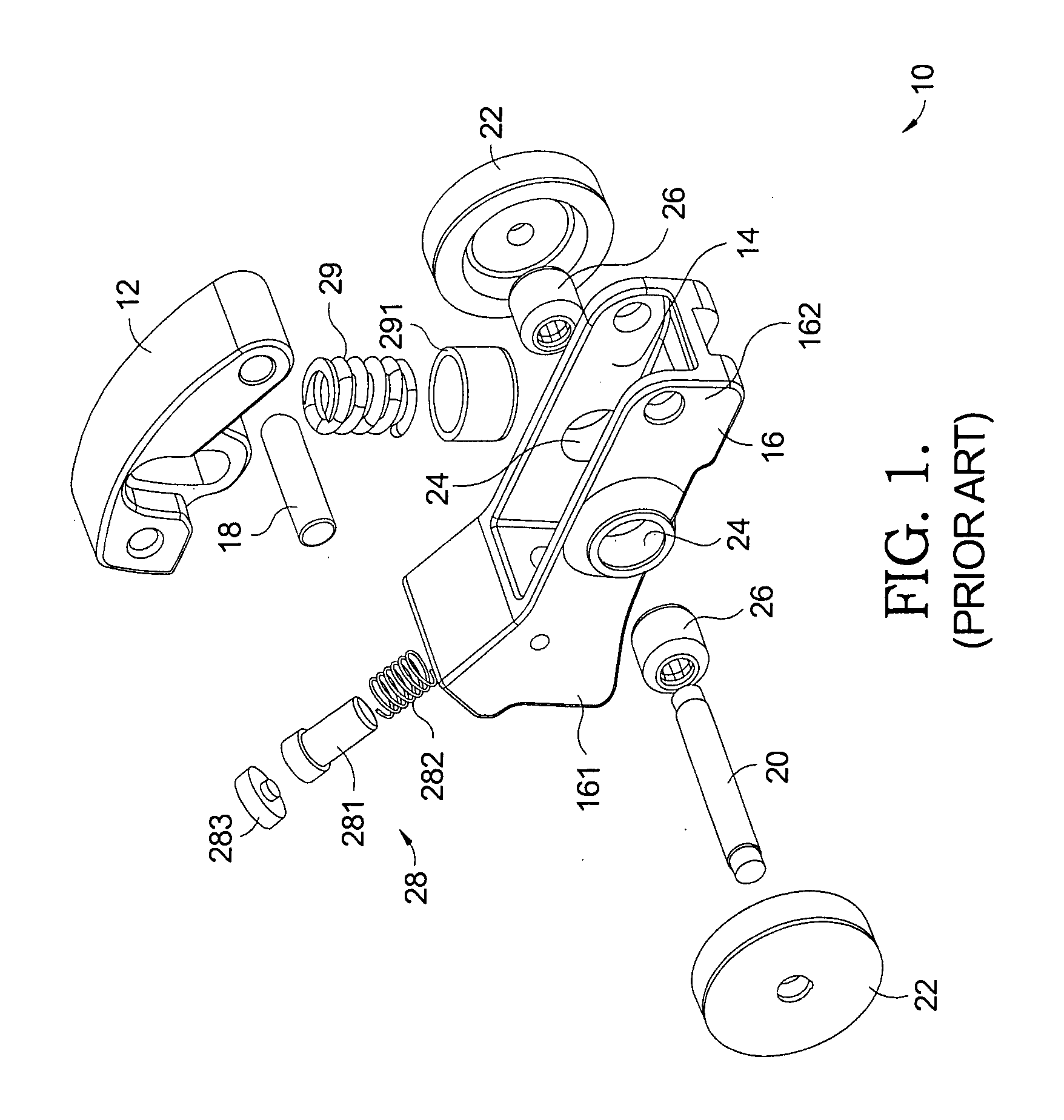
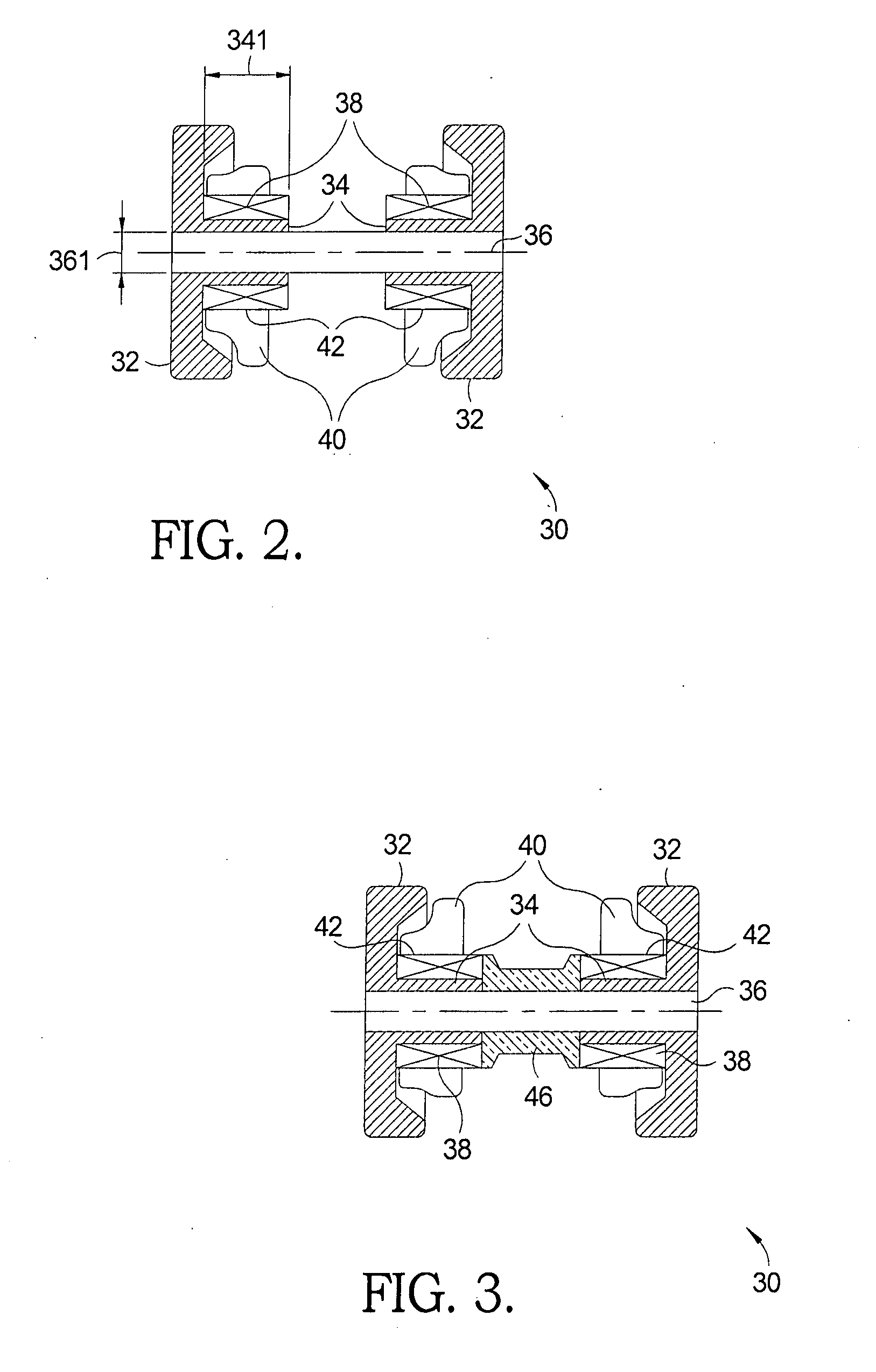
[0028]Referring now to FIG. 2, an inboard bearing design is illustrated. A first roller-shaft assembly 30 in accordance with the invention includes a pair of rollers 32 with an integral inner bearing race 34, a roller shaft 36, and a pair of bearings 38. Roller-shaft assembly 30 may be part of a single-step or two-step roller finger follower assembly, such as RFF assembly 10 as shown in FIG. 1. An outer arm 40 of an RFF assembly includes a pair of openings 42 for receiving bearings 38 and shaft 36. Openings 42 may be configured as outer races for bearings 38 or may receive drawn cup bearings. Bearings 38 may be, for example, roller bearings or needle bearings, such as loose needle or drawn cup needle bearings. Bearings 38 rotatably support inner bearing race 34 and, therefore, permitting rollers 32 to follow lateral cam lobes (not shown). Rollers 32 are lateral follower rollers mounted at opposite ends of roller shaft 36. Rollers 32 may be secured to shaft 36 by using retention meth...
second embodiment
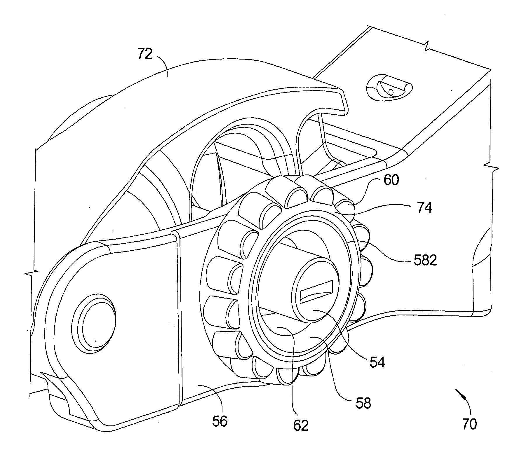
[0032]Referring to FIGS. 4 and 5, an outboard bearing design of a roller finger follower 70 is illustrated. A second roller-shaft assembly 50 in accordance with the invention includes a pair of lateral follower rollers 52 mounted on opposite ends of a roller shaft 54 and a pair of bearings 60 rotatably supporting rollers 52. An outer arm 56 of roller finger follower 70 includes a pair of outward extending bosses 58 that have cylindrical openings 62 for receiving rollers 52 and shaft 54. Roller-shaft assembly 50 is shown in FIG. 5 without rollers 52 installed. Roller-shaft assembly 50 may be part of a single-step or two-step roller finger follower assembly, such as RFF assembly 10 as shown in FIG. 1.
[0033]Shaft 54 is a cross-shaft that extends horizontally through outer arm 56. In a preferred embodiment, shaft 54 is a stepped shaft including step 542. In an alternative embodiment, shaft 54 may be designed as a straight shaft. Shaft 54 may be hardened except for the end-portions follo...
PUM
 Abstract
Description
Claims
Application Information
 - Generate Ideas
- Intellectual Property
- Life Sciences
- Materials
- Tech Scout
- Unparalleled Data Quality
- Higher Quality Content
- 60% Fewer Hallucinations
Browse by: Latest US Patents, China's latest patents, Technical Efficacy Thesaurus, Application Domain, Technology Topic, Popular Technical Reports.
© 2025 PatSnap. All rights reserved.Legal|Privacy policy|Modern Slavery Act Transparency Statement|Sitemap|About US| Contact US: help@patsnap.com