Fuel injector

a fuel injector and injector technology, applied in the direction of valve operating means/release devices, machines/engines, mechanical apparatus, etc., can solve the problem of limited maximum pressure during pressure fluctuations, and achieve safe and reliable function, reduce the load on the diaphragm shell, and increase external pressure

Inactive Publication Date: 2009-05-21
ROBERT BOSCH GMBH
View PDF19 Cites 27 Cited by
  • Summary
  • Abstract
  • Description
  • Claims
  • Application Information

AI Technical Summary

Benefits of technology

[0020]However, it is known that in the case of a relatively small volume inside the diaphragm cell, the final pressure for a given absorption volume, that is, the volumetric difference at maximum pressure and minimum pressure inside the return bore, rises only slightly when the outset volume is large. The diaphragm cell, which is limited in its outside diameter by the installation space, however, under service life conditions can receive only a limited absorption volume. From the typical external pressure / intake volume characteristic curve of the present fuel injector, it can be learned that the absorption volume demand drops with increasing external pressure. Reducing the outset volume produces a steeper characteristic curve of the external pressure over the absorption volume, and as a result, for a given absorption volume, a higher external pressure can be attained. As a result, even at small absorption volumes, safe and reliable function is attained. This makes it possible for the contour of the diaphragms in the entire spring region to be closely spaced because of an asymmetrical disposition of the diaphragm shells. Because of the small initial volume of the diaphragm cell and the resultant steeper pressure / volume characteristic curve, the contact pressure which causes the diaphragm cell to bulge outward when the external pressure drops decreases very quickly, reducing the load on the diaphragm shells and on the weld seam both in the unassembled state and when the diaphragm cell is not in operation.
[0021]A further advantageous embodiment of the present invention provides that the diaphragm cell is filled with helium and has a gas pressure which is greater than the return pressure in the return line or in the recess communicating with the return line. If as the gas that fills the diaphragm cell is selected to be helium, then the tight welding of the diaphragm shells is possible more safely and reliably in process terms and at the same time leads to more favorable properties with regard to changing the gas status. Helium has a high adiabatic exponent, and in highly dynamic events the result is a steeper pressure increase characteristic curve compared to the isothermic fundamental design.

Problems solved by technology

As a result of this effect, the maximum pressure during the pressure fluctuations is limited.

Method used


Image

  • Fuel injector
  • Fuel injector
  • Fuel injector

Examples


Embodiment Construction

[0024]Shown are;

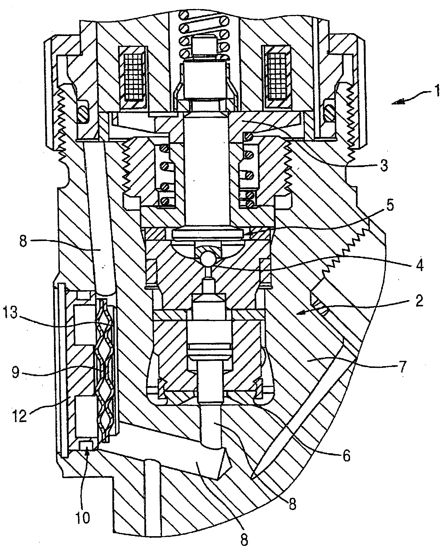
[0025]FIG. 1: a cross section of a fuel injector with means for pressure limitation, and the means are embodied as a diaphragm cell which is integrated inside the injector body;

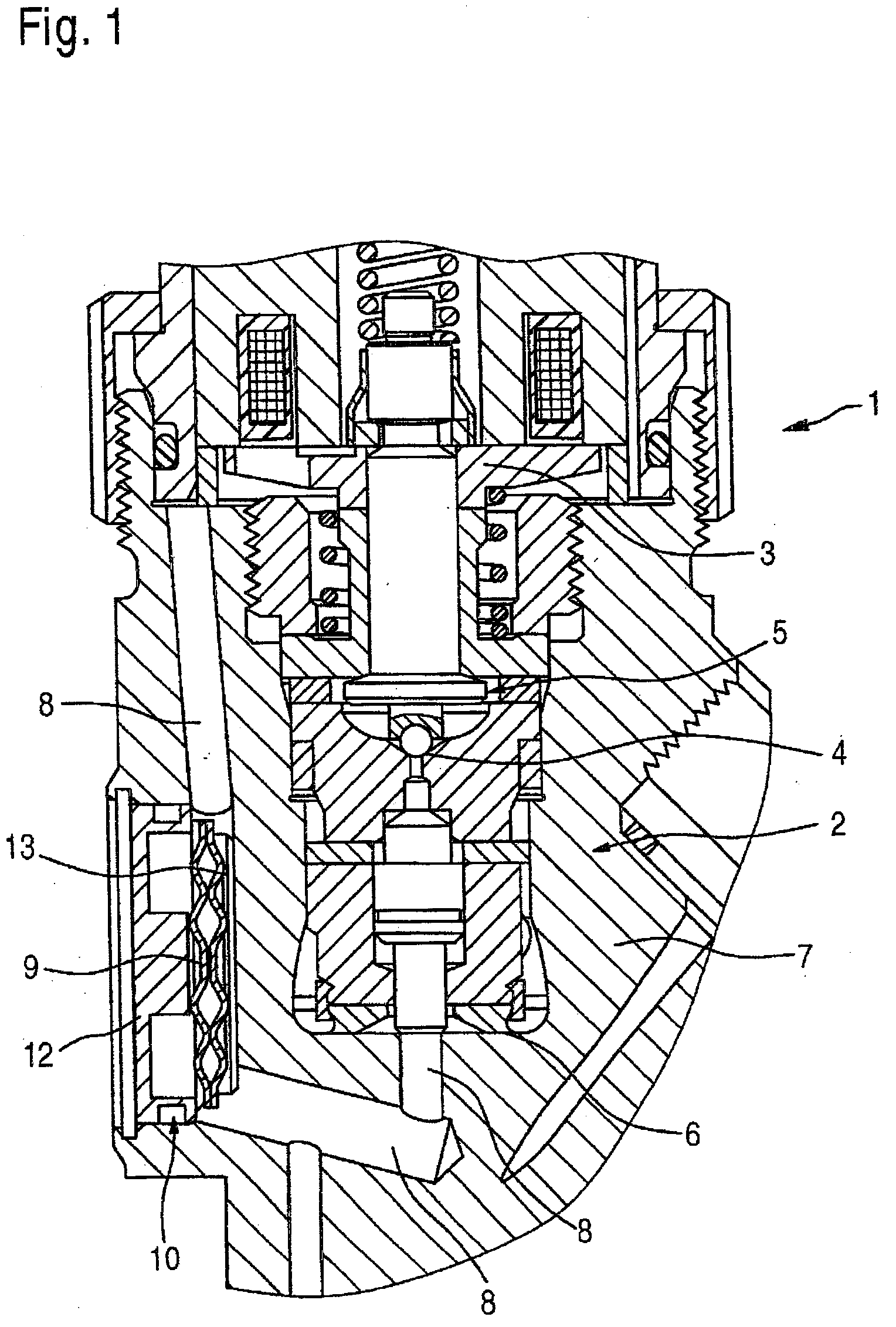
[0026]FIG. 2: a cross section of a detail of the diaphragm cell of FIG. 1 which is integrated inside the injector body;

[0027]FIG. 2a: a cross section of a detail of the damper unit in a further exemplary embodiment;

[0028]FIG. 3: a cross section of a fuel injector with means for pressure limitation, in which the means are embodied as a diaphragm cell which is integrated with a damper housing disposed outside the injector body;

[0029]FIG. 4: a diaphragm cell in accordance with the present invention, which has a symmetrical stroke limiter placed inside it;

[0030]FIG. 5: a further exemplary embodiment of the diaphragm cell with a symmetrically embodied stroke limiter placed inside it;

[0031]FIG. 6a: a first exemplary embodiment of the diaphragm cell, which has a symmetrical disposition of the diaphra...


PUM


Abstract

The invention relates to a fuel injector for injecting fuel into a combustion chamber, having a solenoid valve for controlling a mini-servo valve. A movable armature can be placed in a sealing fashion on a valve seat in a lower armature chamber, wherein in addition the mini-servo valve is held in an injector body and seals a control line against a flat seat. By means of the flat seat, during an actuation of the solenoid valve, the control line can be relieved of pressure from a high fuel pressure to a return pressure into at least one return line. A mechanism for reducing pressure oscillations are provided in the at least one return line, which includes at least one diaphragm cell which is held in a recess and which is placed in fluidic connection with the at least one return bore. A fuel injector with the mechanism for reducing pressure oscillations is therefore created in the at least one return line which operates without a leakage flow and has a simple and effective function.

Description

PRIOR ART[0001]The present invention relates to a fuel injector as generically defined by the preamble to claim 1.[0002]Fuel injectors of the type of interest here serve to control the fuel that is injected into the combustion chamber in an internal combustion engine. They are constructed essentially of a magnet valve and a miniature servo valve, and they actuate a nozzle needle the opening and closing position of which is controllable by the magnet valve, so that injection bores in the injector are opened and closed for injection of the fuel.[0003]A fuel injector of this kind is known from German Patent Disclosure DE 101 59 003 A1. In it, a fuel injector is disclosed which is embodied with a magnet valve for controlling the miniature servo valve, with an armature that can be placed in a valve seat in the lower armature chamber. The lower armature chamber communicates fluidically via bores with a control pressure chamber, and leakage quantities that occur via at least one return bor...

Claims


Application Information

Patent Timeline
Patent Type & Authority Applications(United States)
IPC IPC(8): F02M55/00F02M51/06
CPCF02M47/027F02M2200/315F02M55/04F02M55/002
Inventor JUNGER, DIETEREISENMENGER, NADJAFALTIN, CHRISTIAN
Owner ROBERT BOSCH GMBH
Why Eureka
Try Eureka