3D Video Cube

a cube and video technology, applied in the field of 3d video cubes, can solve the problems of shortchanged 4-d nature of most data, lack of true 360* viewing capability for the audience, and inability to deal with occlusion and opacity, etc., and achieves the effects of strong electrical nonlinearity, long life, and good brightness and luminous efficiency

Active Publication Date: 2009-05-21
KU WILLIAM HSIN MIN
View PDF7 Cites 8 Cited by
  • Summary
  • Abstract
  • Description
  • Claims
  • Application Information

AI Technical Summary

Benefits of technology

[0028]The video cube possesses many of the same advantages that 2-D plasma displays have over other display systems: very strong electrical nonlinearity, discharge switching, intrinsic memory, long lifetime, good brightness and luminous efficiency, rugged and simple structure, high resolution and fidelity, large formats, and tolerance for high temperatures and stray magnetic fields. While the proposed video cube is quite similar to a 2-D gas-discharge display, the use of thin conductive wires in a 3-D grid rather than conductive strips on a bulky substrate permit a more compact and higher resolution true 3-D display with lower voltages and higher pressures. Construction and mechanical alignment should be no more difficult than conventional plasma displays. Most importantly, the video cube offers a unique and effective way to present dynamic, 3-D image information.
[0029]Future enhancements include improving the color fidelity and occlusion / opacity capability of the basic video cube. One design is use a close packed cubic array of coated gas-filled glass beads (FIG. 11). A prototype geometry involves 400 μm diameter beads filled with 3 different mixtures of noble gases (e.g. Ne—Ar, Ne—Kr, and Ne—Xe) which glow at different colors. Adjusting the voltages at crossed wire points would excite different voxels to emit different colors which can be mixed to produce a spectrum of colors. A thin coating of an electrochromic (or liquid crystal material) on each glass bead surface can be electrically controlled to make the voxel more or less transparent. Inner glass beads corresponding to non-visible voxels can be made opaque with proper voltage-current setting between two crossed wires controlling that voxel. This will provide true color solid imaging permitting the video cube to replace conventional display systems in a wide range of applications.

Problems solved by technology

2-D displays have improved greatly in terms of price and performance over the last few years but in many applications the inherent 4-D nature of most data is shortchanged by the lack of a real third spatial dimension in the display device.
The vast majority of 3-D devices require visual aids for the observer or complex mechanical motion in the display, and lack true 360* viewing capability for the audience.
Several static, auto-stereoscopic volumetric display devices have been proposed and built over the last few decades but all of them have certain limitations in terms of spatial resolution, temporal resolution, viewing angle, color fidelity, ability to deal with occlusion and opacity, cost, and complexity of construction and operation (see Volumetric Display devices in Wikipedia).
The cost of the projected prototype system is high, but continued reduction in semiconductor component and plasma display technology costs should bring the cost of the video cube within reach of the commercial market by 2010.

Method used


Image

  • 3D Video Cube
  • 3D Video Cube
  • 3D Video Cube

Examples


Embodiment Construction

C.1 Basic Concept

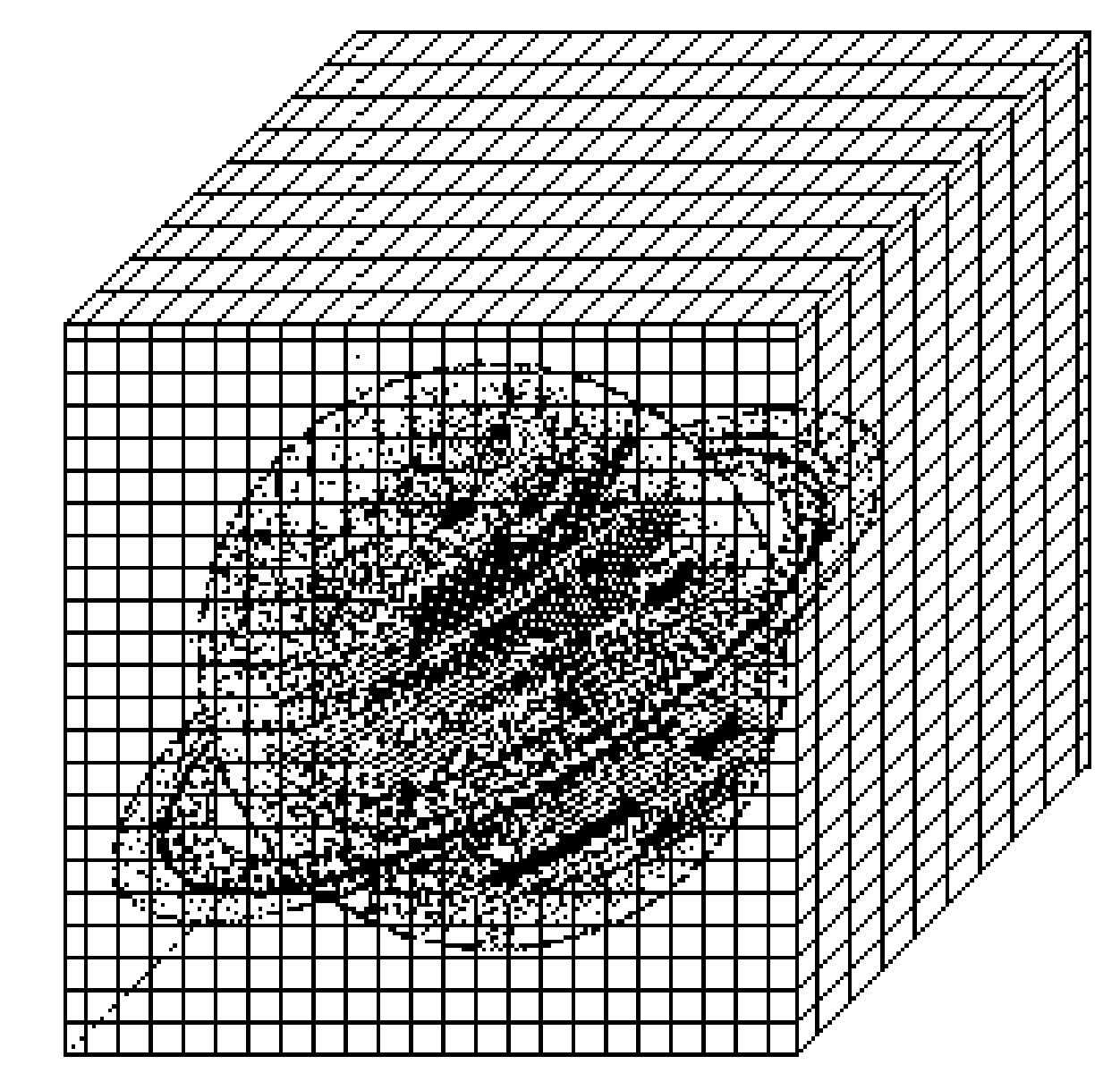
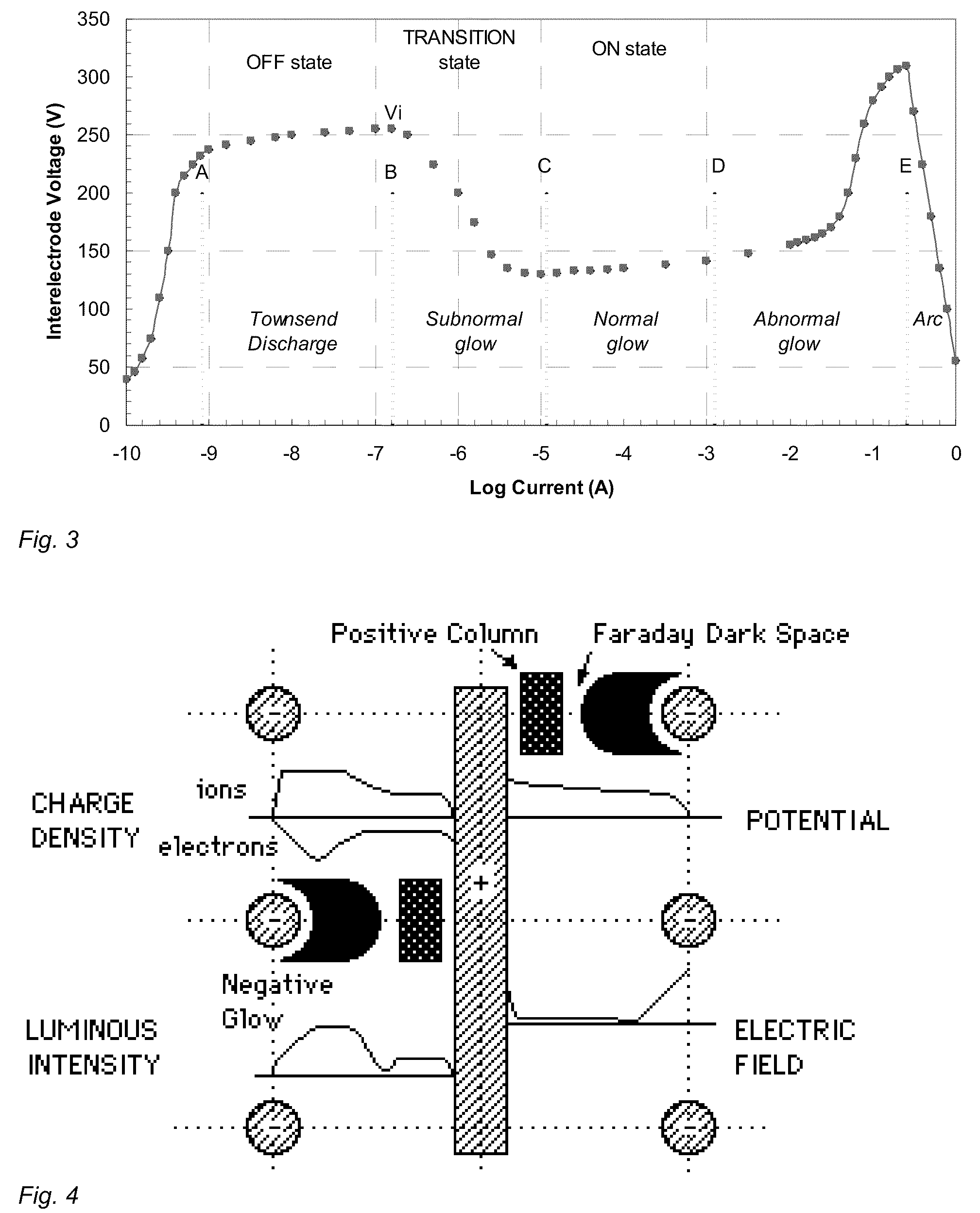
[0005]The video cube operates on the principle of photon emission from a moderate voltage discharge in a low pressure gas. It employs certain technologies already developed for particle physics detectors and gas discharge (plasma) displays.

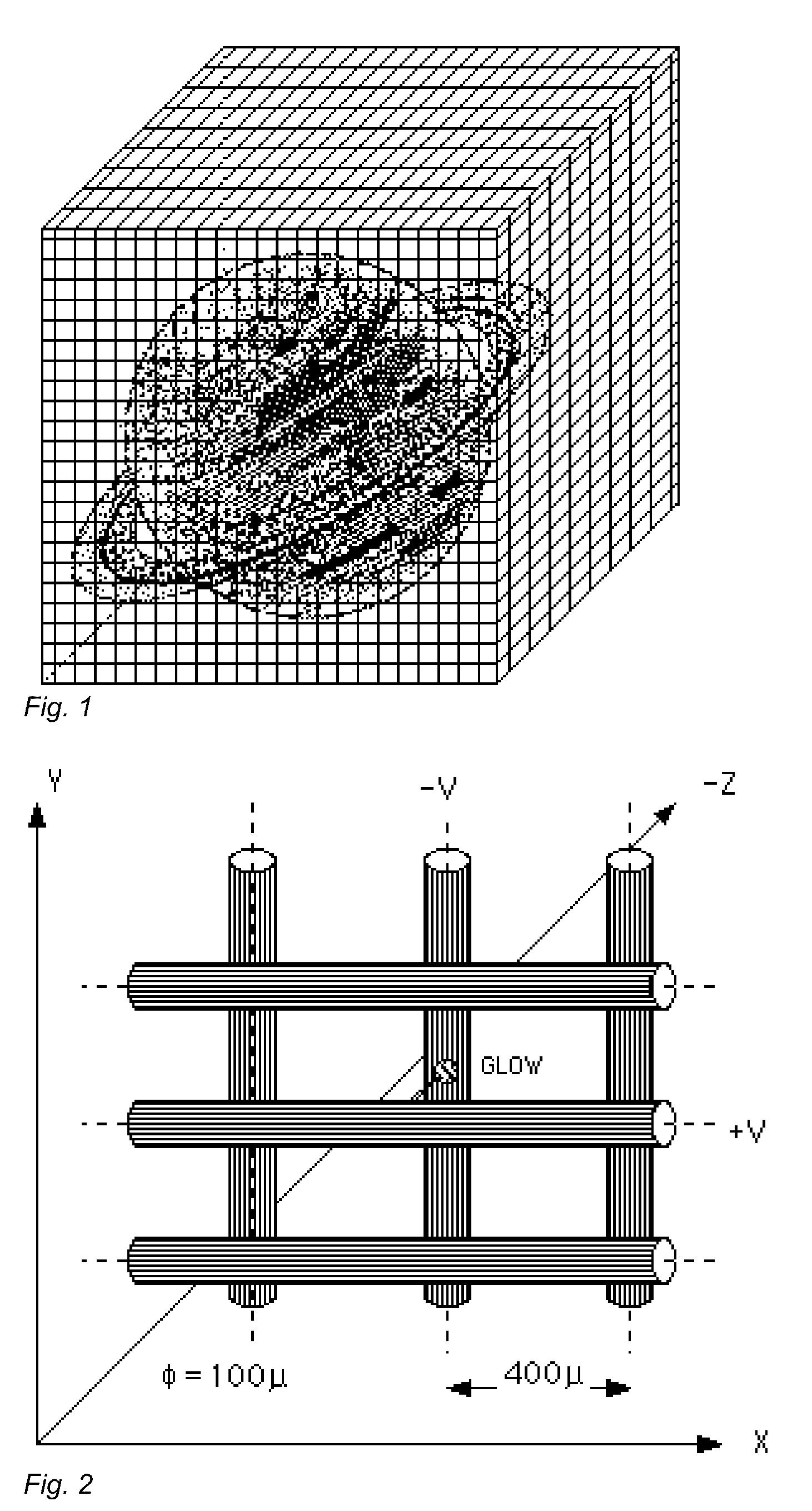
[0006]The prototype video cube consists of a 225×225×225 mm air-tight glass cube (7 mm wall) filled with 600 Torr of Ne—Ar (0.1%) gas. Inside, an open cube structure, consisting of 4 inner walls made from 3 mm thick glass slabs with 100 μm diameter holes, spaced 400×800 μm apart is used as a frame to support a fine grid of wires. Each plane of wires consists of 100 μm diameter glass-coated tungsten wires, spaced 400 μm apart (FIG. 2). Adjacent wire planes are strung perpendicular to one another. These wires are uniformly tensioned (2 N) and then epoxied to the glass frame.

[0007]Transparent external wire leads attached through the bottom and back of the cube may be used to supply power and signal to the inner wires. If a particular...


PUM


Abstract

The present invention is a novel, high resolution, color, three-dimensional (3-D) volumetric display system for dynamic images—the video cube. The video cube consists of an air-tight glass cube filled with a gas mixture and multiple planes of thin wires arranged in alternating orthogonal layers. These wires may be set at voltage potentials capable of producing a glow discharge at the intersection of pairs of wires. Using a computer capable of storing dynamic image data and electronic controllers capable of energizing pairs of wires appropriately at the proper time 3-D dynamic images may be formed from multiple glows between excited wire pairs. The video cube may be used to display complex real-time information from computers and other digital processors with high accuracy for unlimited number of simultaneous unaided observers.

Description

BACKGROUND OF THE INVENTION[0001]As the amount of information generated and stored in digital form has exploded over the last few years, demand for improved systems to display the information processed by new multimedia digital devices has become more critical. The most efficient way for humans to absorb vast amounts of information quickly is visual. 2-D displays have improved greatly in terms of price and performance over the last few years but in many applications the inherent 4-D nature of most data is shortchanged by the lack of a real third spatial dimension in the display device. The vast majority of 3-D devices require visual aids for the observer or complex mechanical motion in the display, and lack true 360* viewing capability for the audience. Several static, auto-stereoscopic volumetric display devices have been proposed and built over the last few decades but all of them have certain limitations in terms of spatial resolution, temporal resolution, viewing angle, color fi...

Claims


Application Information

Patent Timeline
Patent Type & Authority Applications(United States)
IPC IPC(8): H01J17/49H01J17/16
CPCH01J11/10
Inventor KU, WILLIAM HSIN-MIN
Owner KU WILLIAM HSIN MIN
Why Eureka
Try Eureka