

High gain omni-directional antenna
a high-gain, omni-directional technology, applied in the direction of resonant antennas, independent non-interacting antenna combinations, elongated active element feeds, etc., can solve the problems of limiting the width of the frequency band, excessive directivity of omni-directional antennas, etc., to avoid coupling effects, wide broadband, and high impedan
- Summary
- Abstract
- Description
- Claims
- Application Information
AI Technical Summary
Benefits of technology
Problems solved by technology
Method used
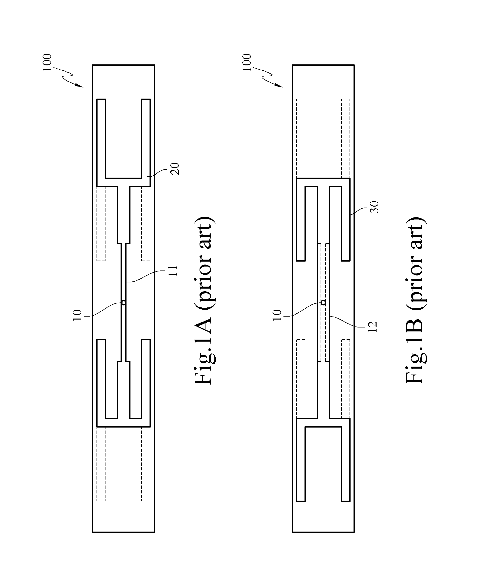
Image

Examples
Embodiment Construction
[0035]The features and practice of the present invention will be illustrated in detail below with the accompanying drawings.
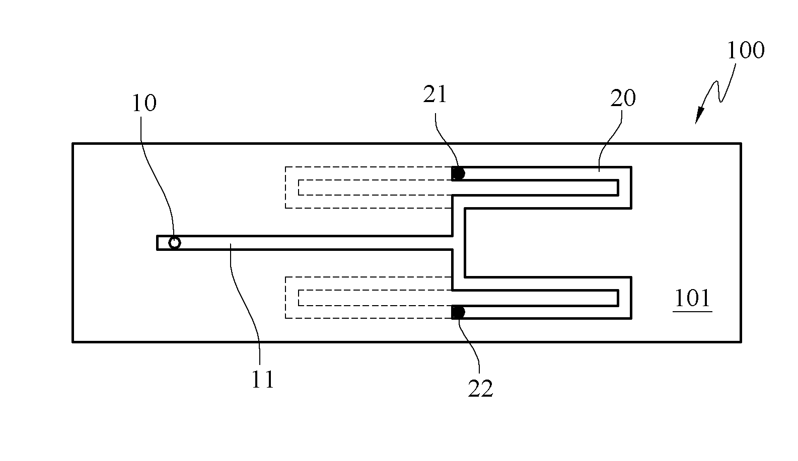
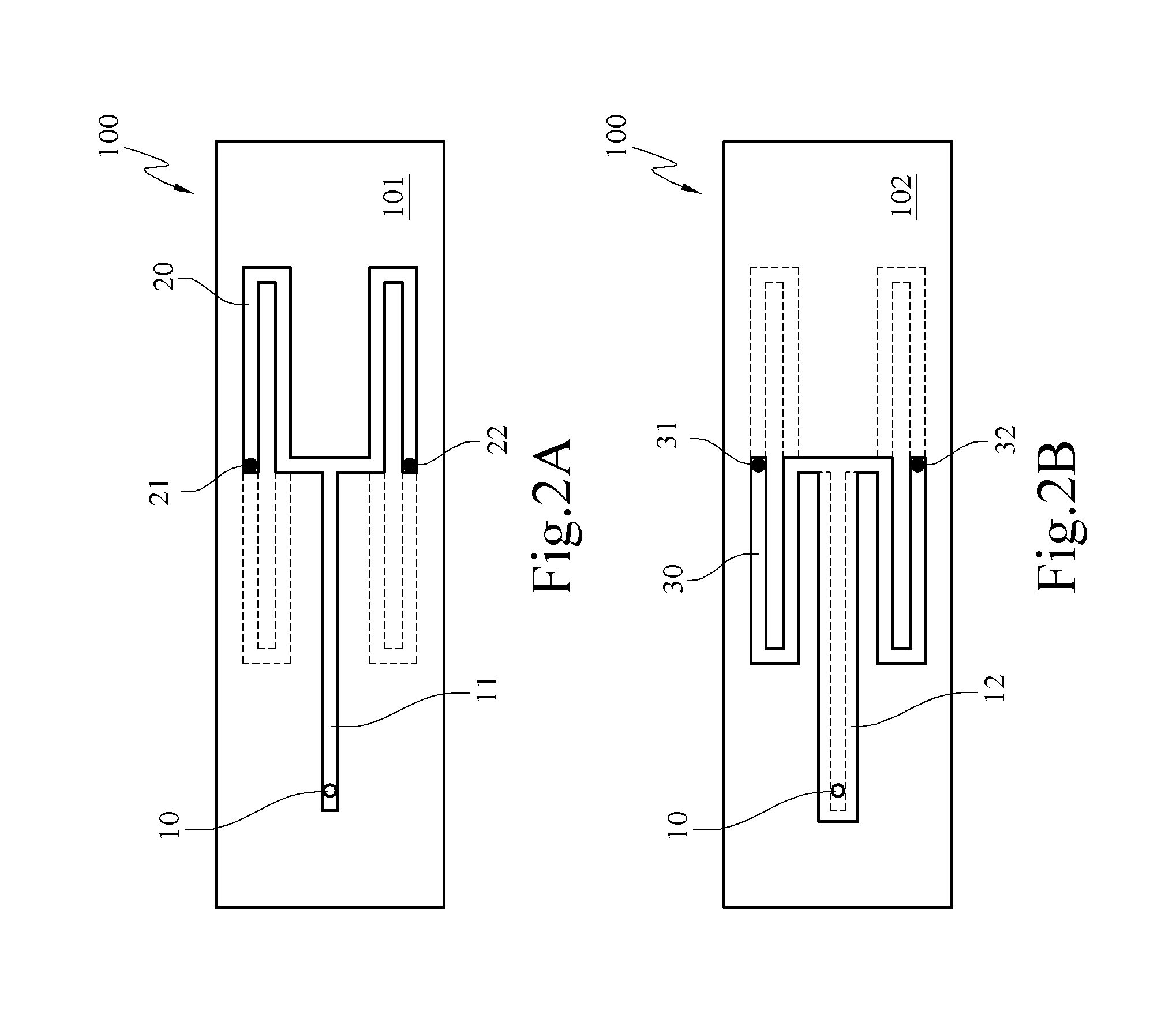
[0036]Referring to FIGS. 2A and 2B, schematic views of a first embodiment of the present invention are shown. FIG. 2A is a schematic view of a first surface according to the first embodiment of the present invention, and FIG. 2B is a schematic view of a second surface according to the first embodiment of the present invention. As shown in FIGS. 2A and 2B, the gain omni-directional antenna includes a signal feed-in portion 10, a first radiating unit 20, and a second radiating unit 30. The substrate 100 is generally a PCB, and definitely, may be substrates of other types. The substrate 100 is a rigid board or a soft flexible board. The material of the rigid board is glassfiber, bakelite, or other materials. The material of the soft flexible board is PI, PET, or other materials. Moreover, the substrate 100 has a first surface 101 and a second surface 102 opposite ...
PUM
 Abstract
Description
Claims
Application Information