
Composite material and optical component using the same

a technology of composite materials and optical components, applied in the direction of optical elements, instruments, coatings, etc., can solve the problems of difficult processing of organic optical materials, difficulty in producing optical components, and becoming finer and more complex, and achieve excellent workability, high refractive index and low dispersion

Active Publication Date: 2009-05-21
PANASONIC CORP
View PDF10 Cites 92 Cited by
  • Summary
  • Abstract
  • Description
  • Claims
  • Application Information

AI Technical Summary

Benefits of technology

[0012]The composite material according to the present invention is a composition exhibiting both a high refractive index and low dispersion in good balance and having excellent workability.
[0013]The optical component according to the present invention is formed using the composite material exhibiting both a high refractive index and low dispersion, and therefore, it exhibits favorable wavelength characteristics and can be reduced in size.

Problems solved by technology

However, inorganic optical materials are difficult to process, and they have the inherent problem of difficulty to produce optical components, which increasingly have become finer and more complex, in a large quantity and at low cost, by using inorganic optical materials.
The problems of organic optical materials include that an optical component formed of an organic optical material alone does not provide a sufficiently high refractive index, and that there are few organic optical materials that are well-balanced in terms of the refractive index and the dispersion.
For example, in the case where a lens serves as the optical component, the fact that the refractive index of the resin is not sufficiently high and the fact that there are few materials that are well-balanced in terms of the refractive index and the dispersion lead to the problem that sufficient characteristics cannot be achieved owing to chromatic aberration or field curvature.
Furthermore, in the case where a solid-state image sensor including an optical waveguide serves as the optical component, a sufficient refractive index difference between the optical waveguide and the surrounding materials cannot be achieved, which results in the problem of a reduced light collection efficiency.

Method used


Image

  • Composite material and optical component using the same
  • Composite material and optical component using the same
  • Composite material and optical component using the same

Examples


first embodiment

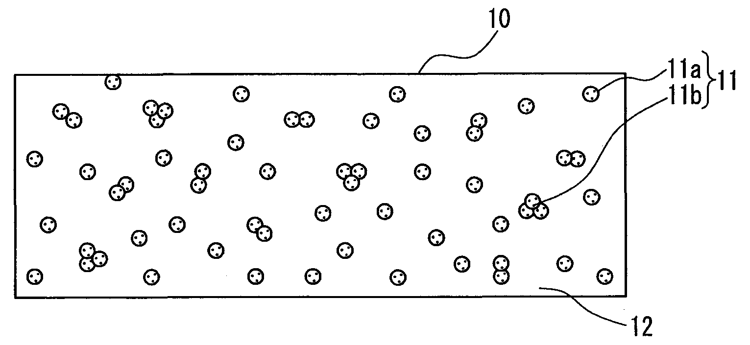
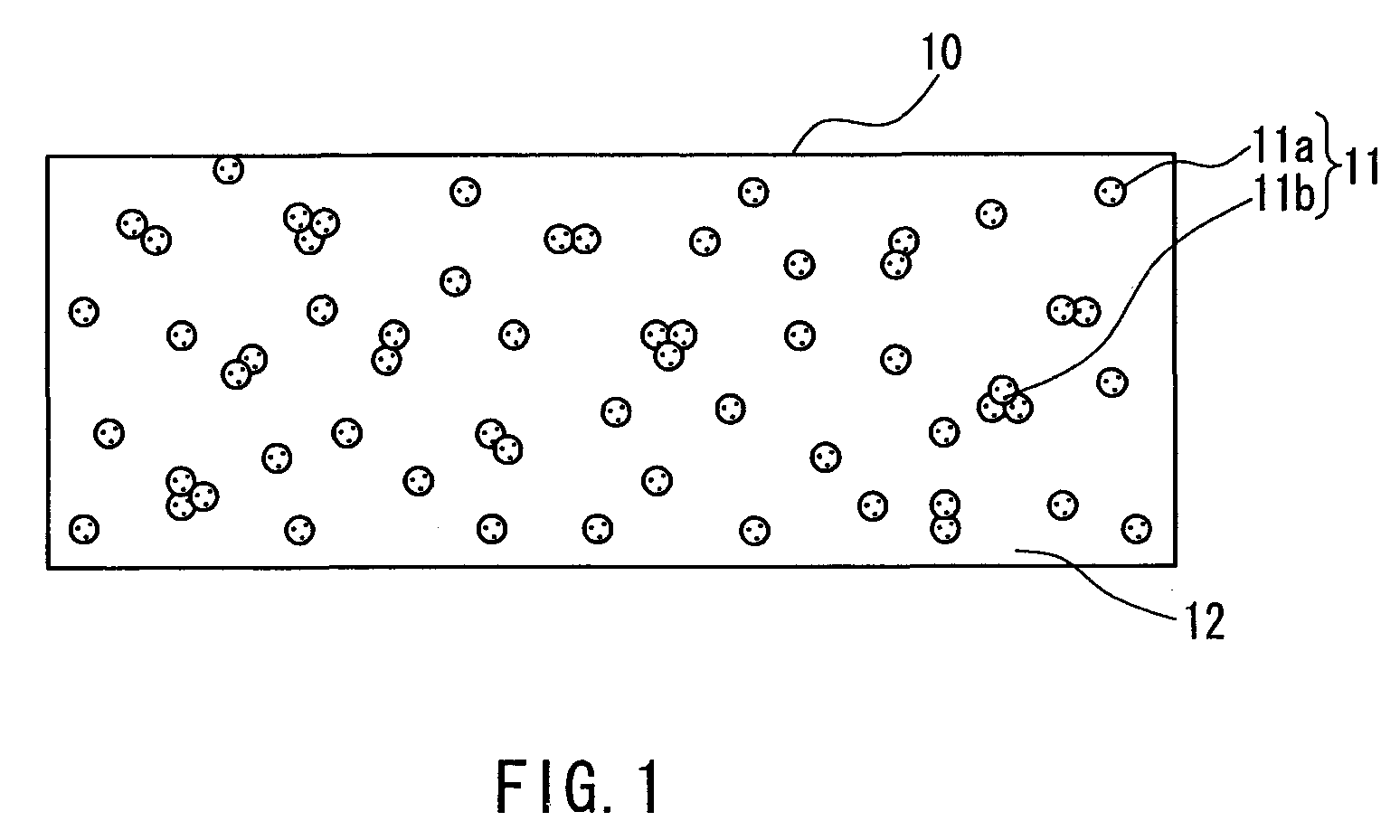
[0047]A composite material 10 according to the first embodiment of the present invention will be described with reference to FIG. 1.

[0048]The composite material 10 according to the first embodiment of the present invention is formed by uniformly dispersing inorganic particles (first inorganic particles) 11 containing at least zirconium oxide in a resin 12 serving as a substrate. Generally, the inorganic particles 11 include primary particles 11a, and secondary particles 11b, which are formed by a plurality of aggregated primary particles 11a. Accordingly, the inorganic particles 11 being uniformly dispersed in the resin 12 means that the primary particles 11a and the secondary particles 11b of the inorganic particles 11 are substantially uniformly dispersed in the composite material 10, without being unevenly distributed in any particular position in the composite material 10. In order for the composite material 10 to have favorable particle dispersibility, it is preferable that the...

second embodiment

[0082]A composite material according to the second embodiment of the present invention will be described with reference to FIG. 7.

[0083]A composite material 60 according to the second embodiment of the present invention is formed by uniformly dispersing first inorganic particles 11 containing at least zirconium oxide and second inorganic particles 13 having a composition different from that of the first inorganic particles 11 and having an Abbe's number νP of not less than 50 in a resin 12 serving as the substrate. Similarly to the first inorganic particles 11, the second inorganic particles 13 generally include primary particles 13a and secondary particles 13b, which are formed by a plurality of aggregated primary particles 13a. Accordingly, the first inorganic particles 11 and second inorganic particles 13 being uniformly dispersed in the resin 12 means that the primary particles 11a and the secondary particles 11b of the inorganic particles 11 and the primary particles 13a and se...

third embodiment

[0126]One embodiment of the optical component using the composite material according to the present invention will be described with reference to FIG. 10.

[0127]In the present invention, examples of the optical component that can be formed using the composite material in which inorganic particles containing at least zirconium oxide are dispersed in a resin include a lens, a diffractive optical element (e.g., a lens, a spatial low-pass filter or a polarizing hologram in which a diffraction grating is formed,), a solid-state image sensor including an optical waveguide, optical fiber, an optical disk substrate, an optical filter and an optical adhesive. Among these, FIG. 10 is a cross-sectional view showing an example of a lens in which a diffraction grating pattern is formed on its surface. It should be noted that the lens shown in FIG. 10 is merely an example, and the present invention is applicable to various other forms.

[0128]A ring-shaped diffraction grating 82a is formed on one si...


PUM

PropertyMeasurementUnit
Lengthaaaaaaaaaa
Fractionaaaaaaaaaa
Nanoscale particle sizeaaaaaaaaaa

Abstract

A composite material (10) includes a resin (12), and first inorganic particles (11) dispersed in the resin and containing at least zirconium oxide. The composite material has a refractive index at the d line nCOMd of not less than 1.60 and an Abbe's number νCOM of not less than 20, and satisfies a relationship nCOMd≧1.8−0.005 νCOM. This composite material exhibits both a high refractive index and low dispersion in good balance, and has excellent workability. Accordingly, using this composite material makes it possible to realize a small optical component having favorable wavelength characteristics.

Description

TECHNICAL FIELD[0001]The present invention relates to a composite material and an optical component using the same. More particularly, the invention relates to a composite material exhibiting a high refractive index and low dispersion and an optical component using the composite material, such as a lens, a diffractive optical element or a solid-state image sensor.BACKGROUND ART[0002]In recent years, optoelectronics have garnered attention as a key technology for realizing, for example, higher-speed information communications or various smaller and lighter electronic devices, and the development of optical materials for achieving these has become imperative.[0003]Conventionally, inorganic materials such as optical glass commonly have been used as optical materials. However, inorganic optical materials are difficult to process, and they have the inherent problem of difficulty to produce optical components, which increasingly have become finer and more complex, in a large quantity and ...

Claims


Application Information

Patent Timeline
IPC IPC(8): G02B5/18G02B1/00C08J7/043C08J7/044C08J7/05
CPCC08J7/047C08J2433/00C08K3/22C08L2312/06C09D133/062G02B1/04C09D163/00C08L2666/54C08J7/0427C08J7/05C08J7/043C08J7/044
Inventor OKADA, YUKAKORENAGA, TSUGUHIROSUZUKI, MASA-AKITAKAHARA, NORIHISA
Owner PANASONIC CORP
Learn More