Method and system of energy integrating and photon counting using layered photon counting detector

Inactive Publication Date: 2009-05-21
GENERAL ELECTRIC CO
View PDF28 Cites 54 Cited by
  • Summary
  • Abstract
  • Description
  • Claims
  • Application Information

AI Technical Summary

Benefits of technology

[0013]The invention in an implementation encompasses a CT system having an improved dose efficienc

Problems solved by technology

A previous photon counting detector saturates at high flux rate and degrades due to pile-up loss of detector quantum efficiency (DQE) and spectral information.
A thin layer of these low atomic number materials may not stop a substantial fraction of the flux.
Thick layers of direct conversion material require a longer transport distance for charge carriers and therefore a greater amount of charge trapping.
Layered detectors may be challenging, difficult, and/or problematic, for example, because the ASIC parts, bonding pads, interconnect, and substrate materials between the top and bottom layers may attenuate the flux to the bottom layer

Method used


Image

  • Method and system of energy integrating and photon counting using layered photon counting detector
  • Method and system of energy integrating and photon counting using layered photon counting detector
  • Method and system of energy integrating and photon counting using layered photon counting detector

Examples


Embodiment Construction

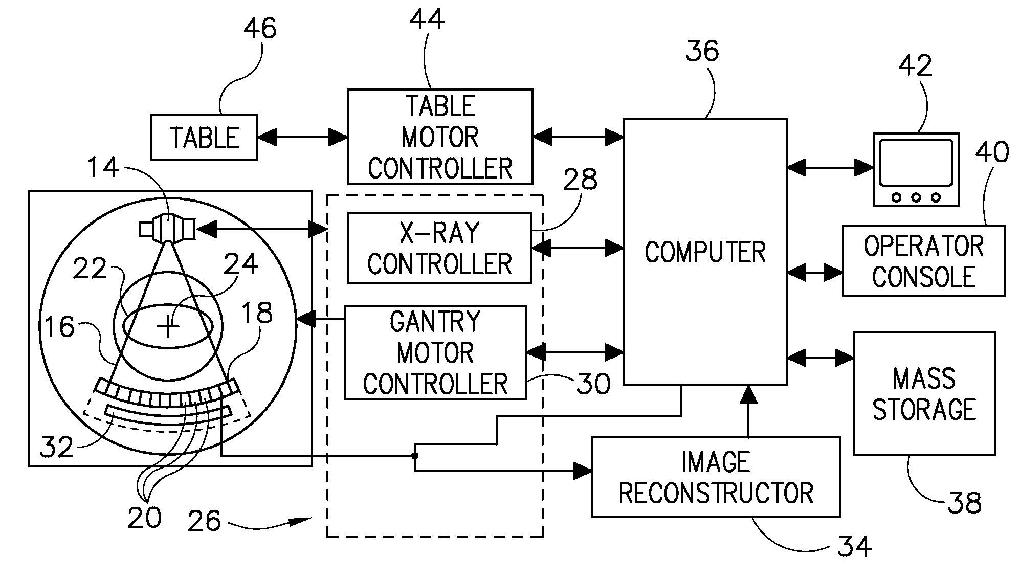
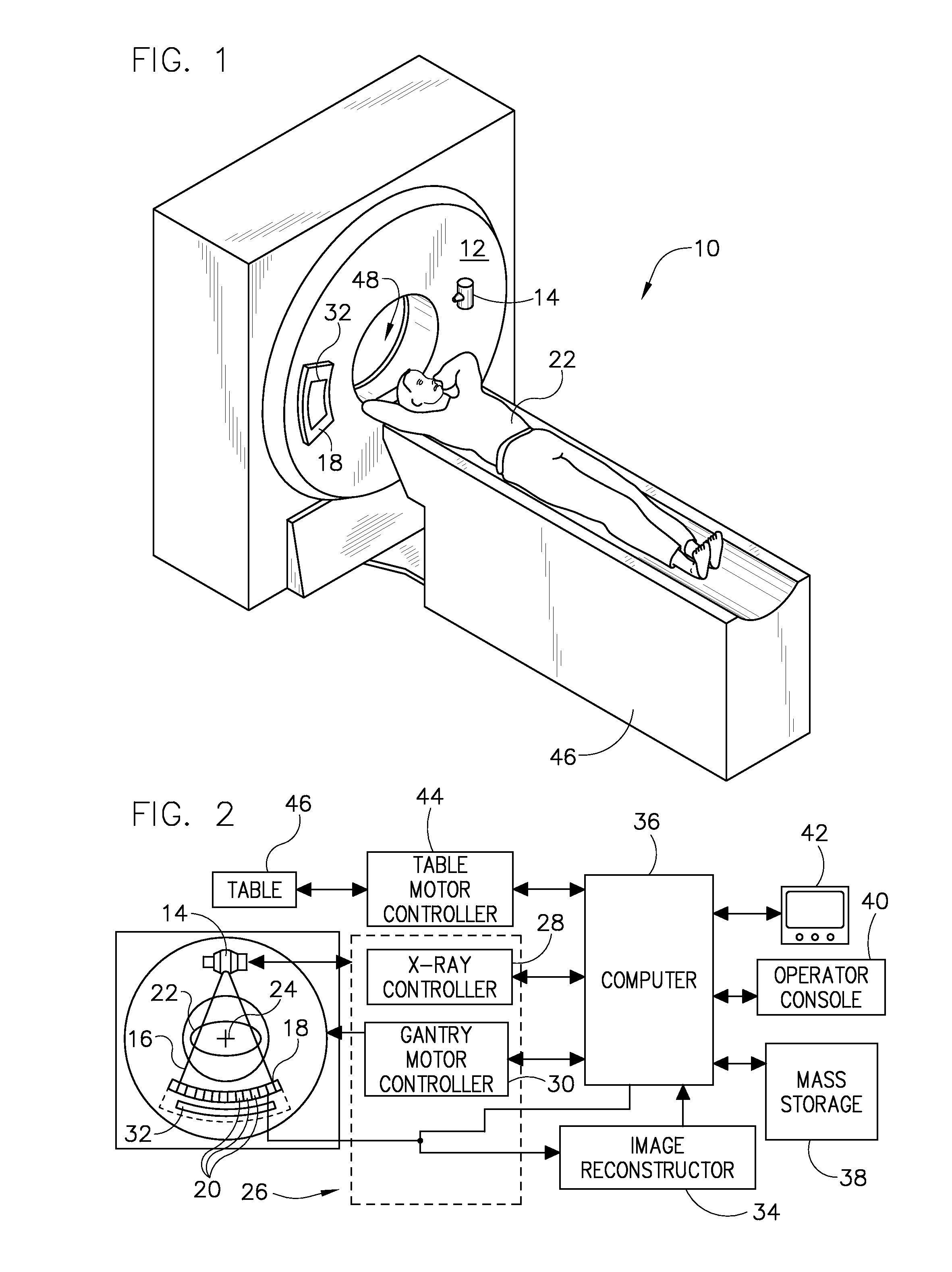
[0029]Diagnostics devices typically comprise x-ray systems, magnetic resonance (MR) systems, ultrasound systems, computed tomography (CT) systems, positron emission tomography (PET) systems, and other types of imaging systems. Applications of x-ray sources comprise imaging, medical, security, and industrial inspection applications. The operating environment described herein includes a 64-slice CT system. However, it will be appreciated by those skilled in the art that an implementation is also applicable for use with single-slice or other multi-slice configurations. More generally, an implementation is employable for detection and conversion of x-rays. However, one skilled in the art will further appreciate that an implementation is employable for the detection and conversion of other high frequency electromagnetic energy, high frequency polychromatic electromagnetic energy, and / or radiographic energy. An implementation is employable with a “third generation” CT scanner and / or other...


PUM


Abstract

A diagnostic imaging system includes an x-ray source that emits a beam of x-ray energy toward an object to be imaged and an energy discriminating (ED) detector that receives the x-ray energy emitted by the x-ray energy source. The ED detector includes a first layer having a first thickness, wherein the first layer comprises a semiconductor configurable to operate in at least an integrating mode and a second layer having a second thickness greater than the first thickness, and configured to receive x-rays that pass through the first layer. The system further includes a data acquisition system (DAS) operably connected to the ED detector and a computer that is operably connected to the DAS. The computer is programmed to identify saturated data in the second layer and substitute the saturated data with non-saturated data from a corresponding pixel in the first layer.

Description

BACKGROUND OF THE INVENTION[0001]The present invention relates generally to diagnostic imaging and, more particularly, to a method and apparatus for high flux rate imaging with energy discrimination, such as in computed tomography (CT) applications.[0002]Diagnostics devices comprise x-ray systems, magnetic resonance (MR) systems, ultrasound systems, computed tomography (CT) systems, positron emission tomography (PET) systems, and other types of imaging systems. Typically, in CT imaging systems, an x-ray source emits a fan-shaped beam toward a subject or object, such as a patient or a piece of luggage. Hereinafter, the terms “subject” and “object” shall include anything capable of being imaged. The beam, after being attenuated by the subject, impinges upon an array of radiation detectors. The intensity of the attenuated beam radiation received at the detector array is typically dependent upon the attenuation of the x-ray beam by the subject. Each detector element of the detector arra...

Claims


Application Information

Patent Timeline
IPC IPC(8): A61B6/00G01T1/20
CPCA61B6/032A61B6/4241G01T1/249G01T1/20G01T1/242A61B6/482
Inventor TKACZYK, JOHN ERICSHORT, JONATHAN D.DU, YANFENGLI, WENWU, XIAOYE
Owner GENERAL ELECTRIC CO
Why Eureka
Try Eureka