Microfluidic device
- Summary
- Abstract
- Description
- Claims
- Application Information
AI Technical Summary
Benefits of technology
Problems solved by technology
Method used
Image

Examples
first embodiment
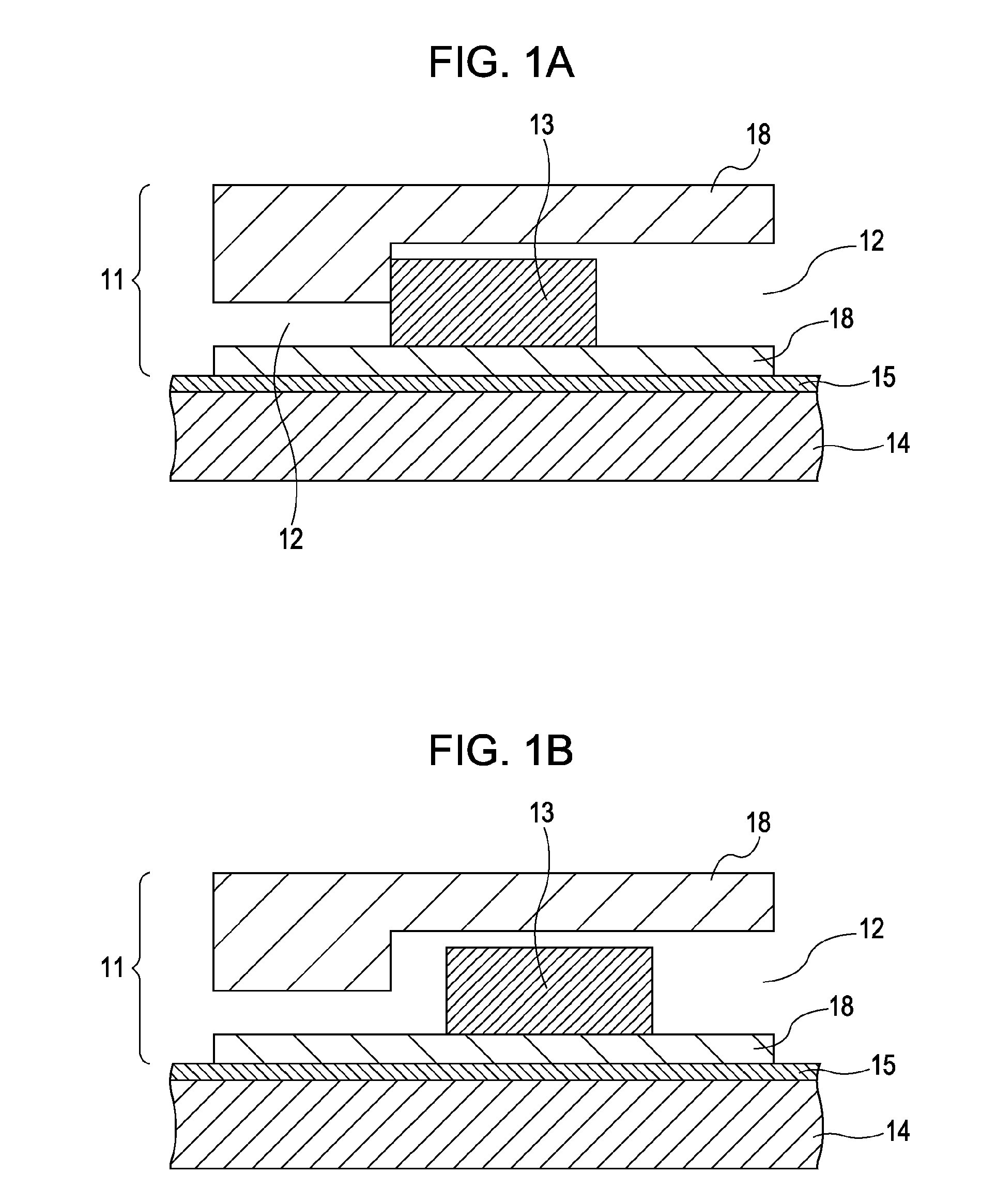
[0028]FIGS. 1A and 1B are cross-sectional views each showing a microfluidic device according to this embodiment.
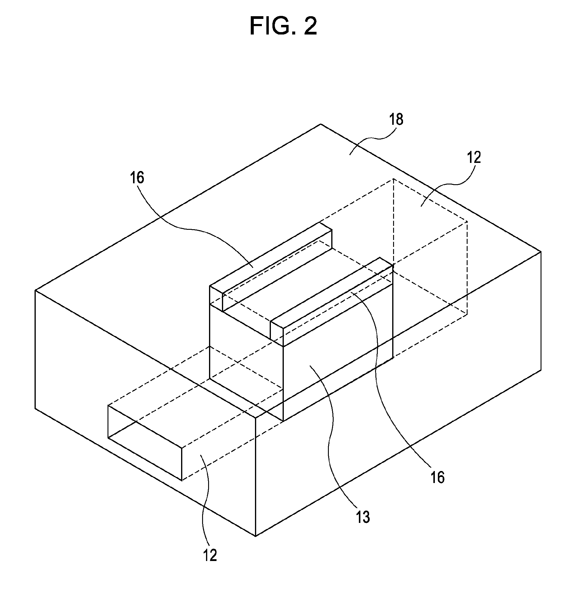
[0029]FIG. 2 is a perspective view schematically showing a microfluidic chip provided in the microfluidic device. In FIG. 2, an upper portion of a substrate is not illustrated so that the inner structure of the microfluidic chip is apparent. The microfluidic device includes a microfluidic chip 11 and an ultrasonic stator 14. The ultrasonic stator 14 has a holding portion 15 to hold the microfluidic chip 11. The microfluidic chip 11 is held by the holding portion 15. Holding of the microfluidic chip 11 by the holding portion 15 may use an attractive force such as, for example, a magnetic force, a vacuum force, or an electrostatic force. Also, the microfluidic chip 11 can be held in a replaceable manner.
[0030]The microfluidic chip 11 is formed of a substrate 18 with a very small channel 12 having, for example, a rectangular cross section. In the channel 12, pumping, mixing a...
second embodiment
[0038]Now, a structure of a microfluidic device according to another embodiment is described. FIG. 3 is a perspective view schematically showing a microfluidic device according to this embodiment. The microfluidic device includes a microfluidic chip 11, an ultrasonic stator 14, and a detection system 19. The microfluidic chip 11 is held by a holding portion (not shown) formed at the ultrasonic stator 14. The structure of the microfluidic chip 11 in this embodiment is similar to that of the microfluidic chip 11 illustrated in FIG. 2, except that a reference scale 17a and a scale 17b are additionally provided. The reference scale 17a is fixed to the substrate 18, whereas the scale 17b is fixed to the valve 13. The reference scale 17a and the scale 17b are provided at opposite positions. The detection system 19 can detect the reference scale 17a and the scale 17b. The detection system 19 is arranged above the valve 13 of the microfluidic chip 11 in a noncontact manner. The position of ...
third embodiment
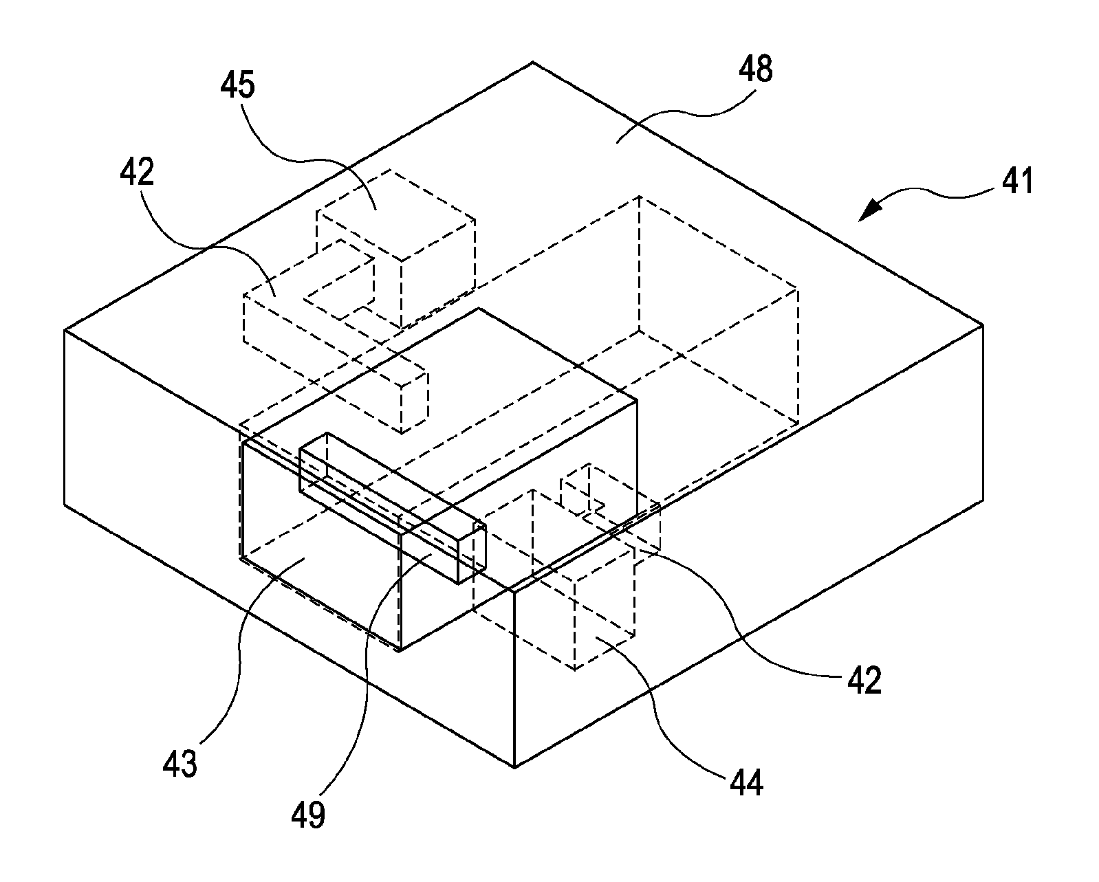
[0042]Next, another embodiment of a microfluidic chip is described. FIG. 4A is a perspective view schematically showing a microfluidic chip in a valve-closing state, and FIG. 4B is a perspective view schematically showing the microfluidic chip in a valve-opening state, according to this embodiment. Also, FIG. 5 is a perspective view specifically showing a valve of the microfluidic chip in FIGS. 4A and 4B.
[0043]A microfluidic chip 41 is formed of a substrate 48 with a very small channel 42. A first chamber 44 is provided at an upstream end portion of the channel 42, and a second chamber 45 is provided at a downstream end portion of the channel 42. The first chamber 44 is a flow source of fluid to be used in analysis. The first chamber 44 contains, for example, a reagent or an analyte. The second chamber 45 is an area for reaction of the reagent or the analyte flowing from the first chamber 44.
[0044]Also, a valve 43 is provided in the microfluidic chip 41 so as to decouple an upstream...
PUM
 Abstract
Description
Claims
Application Information
 - R&D
- Intellectual Property
- Life Sciences
- Materials
- Tech Scout
- Unparalleled Data Quality
- Higher Quality Content
- 60% Fewer Hallucinations
Browse by: Latest US Patents, China's latest patents, Technical Efficacy Thesaurus, Application Domain, Technology Topic, Popular Technical Reports.
© 2025 PatSnap. All rights reserved.Legal|Privacy policy|Modern Slavery Act Transparency Statement|Sitemap|About US| Contact US: help@patsnap.com